


3 COM Express™ Module sizes
Copyright © COM Express™ Extension
Specification Rev 013
11
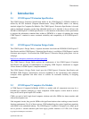
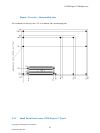
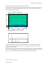
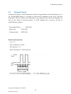
The PCB size for the nano module is defined as 55mm x 84mm.
The holes shown in this drawing are intended for mounting the module / heat-spreader combination to
the carrier board. An independent, implementation specific set of holes and spacers shall be used to
attach the heat-spreader to the module.
Figure - Small Form Factor nano
All dimensions are shown in millimetres. Tolerances should be ± 0.25mm [±0.010"], unless noted
otherwise. The tolerances on the module connector locating peg holes (dimensions [16.50, 6.00])
should be ± 0.10mm [±0.004"].
The 220 pin connector shall be mounted on the backside of the PCB and is seen “through” the board in
this view. The X mounting holes shown should use 6mm diameter pads and should have 2.7mm plated
holes, for use with 2.5mm hardware. The pads should be tied to the PCB ground plane.
51
8
55
Holes Compatible to COM Express™
ecification
COM
E
xpress
™ Type 1
80
4
4