


4 Signal Description
Copyright © COM Express™ Extension
Specification Rev 013
12
4 Signal Description
4.1 Graphic Signal Description
Based on the different available graphic interfaces offered by the different chipsets from silicon
vendors including Intel, ATI, VIA, etc., there is a need for optional assignment in addition to the ones
already defined by PICMG in the COM.0 specification. These will allow for ease when integrating
upcoming new graphic interfaces while still assuring compatibility of COM Express™ compliant
modules and carrier boards.
Graphic signals are defined on Row C and Row D.
The following table describes the signal uses up on the required graphic interface.
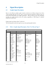
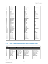
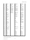
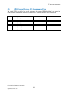
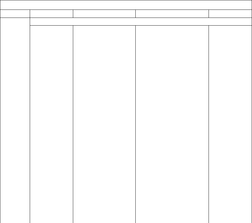
4.1.1 Table – Graphic Signal Description - Row C for Pin-out Type 2
Row C
Definition
PCIE x 16 SDVO TMDS(DVI)/HDMI/DVO Display Port
Pin No. Pin Name
C52 PEG_RX0+ SDVO_TVCLK+ HDMI_TVCLKIN
C53 PEG_RX0- SDVO_TVCLK- HDMI_TVCLKIN#
C54 TYPE0# TYPE0# TYPE0# TYPE0#
C55 PEG_RX1+ SDVOB_INT+
C56 PEG_RX1- SDVOB_INT-
C57 TYPE1# TYPE1# TYPE1# TYPE1#
C58 PEG_RX2+ SDVO_FLDSTALL+ TMDS_DDC_DAT DPB_AUX
C59 PEG_RX2- SDVO_FLDSTALL- TMDS_DDC_CLK DPB_AUXB
C60 GND (FIXED) GND (FIXED) GND (FIXED) GND (FIXED)
C61 PEG_RX3+ TMDS_HPD DPB_HPD
C62 PEG_RX3-
C63 RSVD RSVD RSVD RSVD
C64 RSVD RSVD RSVD RSVD
C65 PEG_RX4+
C66 PEG_RX4-
C67 RSVD RSVD RSVD RSVD
C68 PEG_RX5+ SDVOC_INT+
C69 PEG_RX5- SDVOC_INT-
C70 GND (FIXED) GND (FIXED) GND (FIXED) GND (FIXED)
C71 PEG_RX6+ TMDS_2_DDC_DAT DPC_AUX
C72 PEG_RX6- TMDS_2_DDC_CLK DPC_AUXB
C73 SDVO_DATA SDVO_DATA
C74 PEG_RX7+ TMDS_2_HPD DPC_HPD
C75 PEG_RX7-
C76 GND GND GND
C77 RSVD RSVD RSVD