


. . . . . . . . . . . . . . . . . . . . . . . . . . . . . .
1-5
1124 100Base-TX Repeater User Guide
Writer: Chris Seiter Project: Introduction Comments: 185810-001/707119-001
File Name:10024_1.DOC Last Saved On:3/13/96 5:15 PM
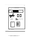
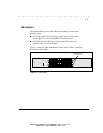
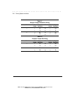
LED Indicators
The repeater features several LED indicators that help you monitor the
repeater's status.
■ The LEDs on the left side of the front panel show the status of the
power supplies as well as the 100Base-TX collision status.
■ The LEDs above the RJ-45 ports indicate the link, activity, and
partition status for each of the ports.
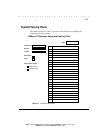
Figure 1-4 shows the LED arrangement for the repeater; Table 4-1 describes
the functions of the LEDs.
MDI
MDI-X
MDI-X
1
13
2
14
3
15
4
16
5
17
6
18
7
19
8
20
9
21
10
22
11
23
12
24
COL
PWR A
PWR B
MDI-X
(24) RJ-45 UTP Ports
(for 100Base-TX)
Figure 1-4. LED Indicators