


. . . . . . . . . . . . . . . . . . . . . . . . . . . . .
3-4 Installing the Repeater
Writer: Chris Seiter Project: Installing the Repeater Comments: 185810-001/707113-001
File Name:10024_3.DOC Last Saved On:3/14/96 11:56 AM
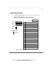
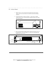
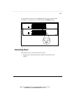
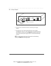
The default setting for the uplink switches is MDI-X (Media Dependent
Interface-Reversed, that is, a standard IN repeater port).
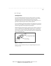
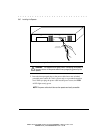
To convert Port 1 or Port 12 to an uplinkable OUT port, use a small, slotted
screwdriver, or a similar tool, to set the switch to the MDI position (Figure 3-
4).
NOTE: IEEE specifications allow only one 100 Mb/s uplink connection per collision
domain. Therefore, you cannot uplink to two 100 Mb/s repeaters. However, you
can use both uplink ports for 10 Mb/s uplink connections.
MDI-X
MDI-X
1
13
2
14
3
15
4
16
5
17
6
18
7
19
8
20
9
21
10
22
11
23
12
24
COL
PWR A
PWR B
MDI MDI-X
MDI MDI-X
Standard
"IN" Repeater Port
(Default)
Uplinkable
"OUT" Port
Figure 3-4. Uplink Switch (Default Setting)
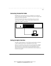
Interconnecting Repeaters
You can interconnect two repeaters, providing up to 48 ports in the same
collision domain (segment). You can also connect the repeater to a single-
speed repeater (10 Mb/s or 100 Mb/s).
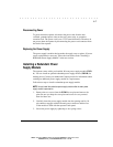
To connect the repeater to another repeater, set the appropriate uplink switch
as described in “Setting the Uplink Switches” in this chapter and connect the
repeaters as shown in Figure 3-5.
NOTE: At 100 Mb/s, the maximum cable distance between two repeaters is 5
meters (16.4 feet) while still allowing a maximum distance of 100 meters (328
feet) for repeater to workstation/server connections. At 10 Mb/s, the distance
between two repeaters can be up to 100 meters.