


United States January 2, 2003
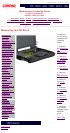
Maintenance & Service Guide
Presario 1600 Series
Models: 1650 and 1655
| Home Page | Notice | Preface | Product Description | Troubleshooting
Illustrated Parts Catalog | Removal & Replacement Procedures | Specifications
Pin Assignments | Battery Pack Operations
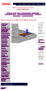
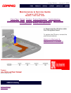
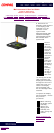
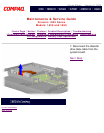
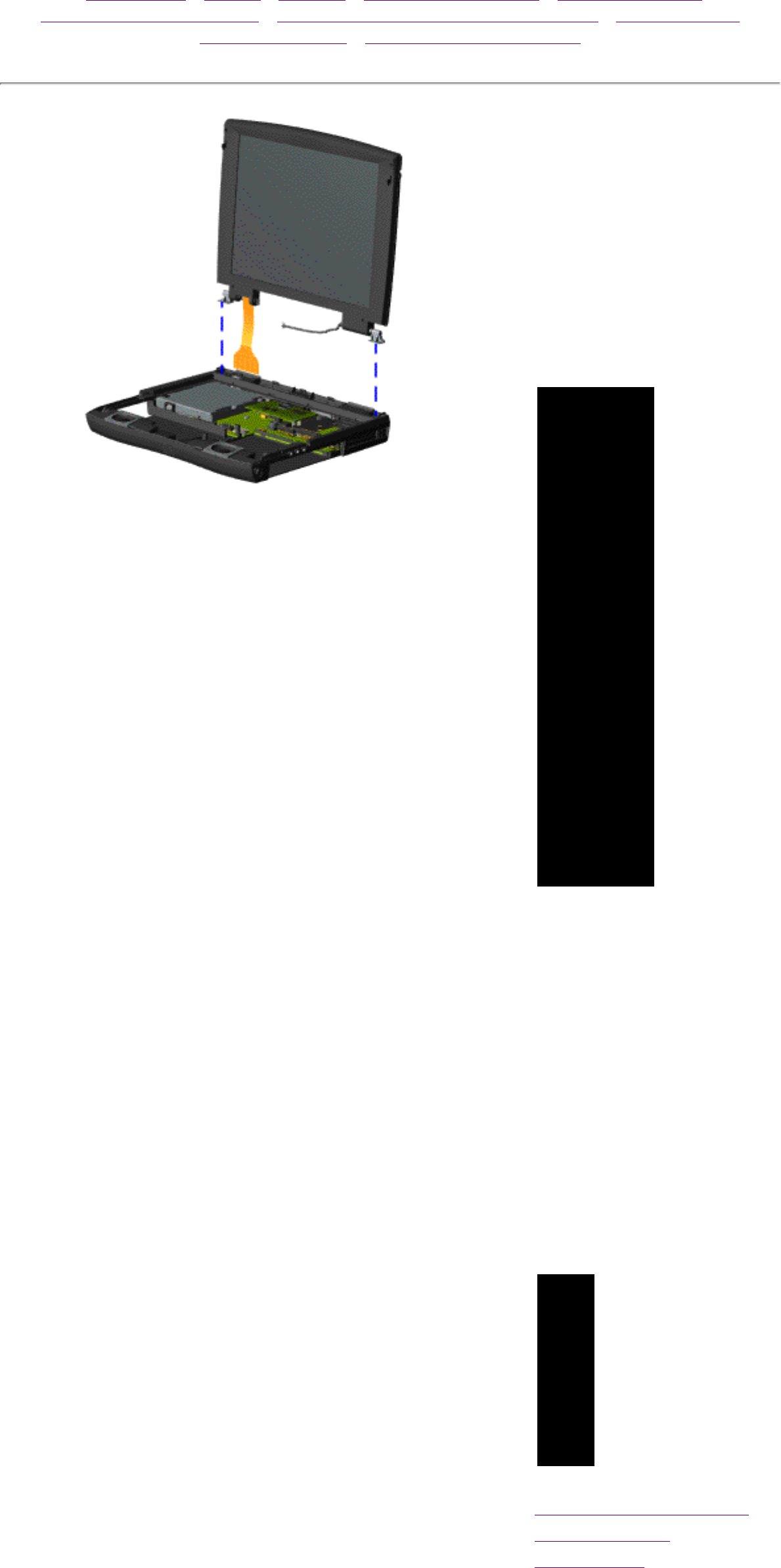
9. Disconnect the
backlight cable attached
to the display panel
assembly from the
connector on the
system board.
Disconnect the flex cable
attached to the display
panel assembly from the
ZIF connector on the
system board.
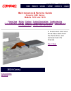
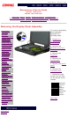
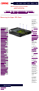
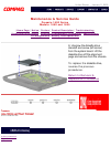
IMPORTANT:
The flex
cable for
the 13.3''
TFT display
panel will
contain a
connector
which will
need to be
removed
before
pulling the
flex cable
attached to
the display
panel
assembly
through
the slot on
the Upper
CPU cover.
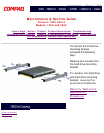
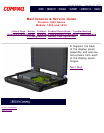
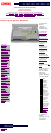
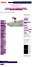
10. Gently pull the flex
cable attached to the
display panel assembly
through the slot on the
Upper CPU cover and
remove the display
panel assembly with
flex and backlight cable
attached.
To replace the display
panel assembly, reverse
the previous
procedures.
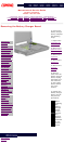
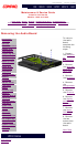
NOTE:
When removing
the display panel
assembly,
observe the
display panel
assembly flex
cable routing and
position.
Return to Removal &
Replacement
Procedures
privacy statement
legal notices