


f.
Top cover (see
Top cover on page 64)
g.
Audio board (see
Audio board on page 74)
h.
USB/power connector board (see
USB/power connector board on page 70)
When replacing the system board, be sure that the following components are removed from the defective
system board and installed on the replacement system board:
●
Memory modules (see
Memory module on page 44)
●
RTC battery (see
RTC battery on page 46)
●
WLAN module (see
WLAN module on page 47)
●
Bluetooth module (see
Bluetooth module on page 67)
●
ExpressCard assembly (see
ExpressCard assembly on page 68)
●
Fan/heat sink assembly (see
Fan/heat sink assembly on page 75)
●
Processor (see
Processor on page 78)
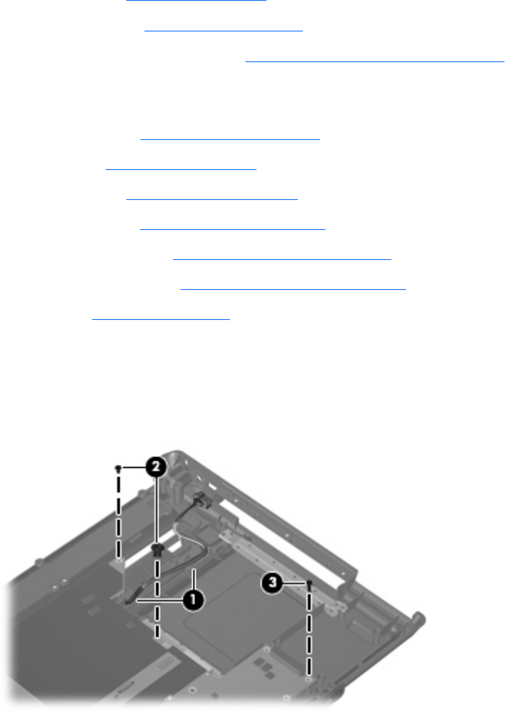
Remove the system board:
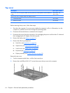
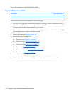
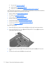
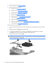
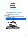
1. Remove the USB/power connector board cable (1) from the clips built into the base enclosure.
2. Remove the Phillips PM2.5×4.0 screw (2) and the Phillips PM2.0×7.0 screw (3) that secure the
system board to the base enclosure.
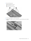
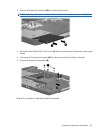
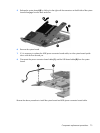
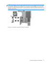
3. Use the optical drive connector (1) to lift the right side of the system board (2) until it rests at an
angle.
4. Disconnect the audio board cable (3) from the system board.
72 Chapter 4 Removal and replacement procedures