


Appendix C - LED Patterns and Test Switch Settings 37
Appendix C - LED Patterns and
Test Switch Settings
RISC Router 3500R LED Patterns
The RISC Router 3500R uses a number of light patterns on its front
LED bars to indicate operating conditions.
Power On, No Traffic
The router will scan through the left (Ethernet) LED bar, from left to
right, illuminating one element at a time.
v
Note: Lights 1 and 10 on the Ethernet bar are directly connected to
the router’s 10BaseT interface and indicate 10BaseT link (1) and
10BaseT polarity (10).
Traffic Indicators (Ethernet LED Bar)
Scan from 2 to 5: Ethernet transmit packet
Scan from 9 to 6: Ethernet receive packet
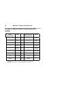
Other Indicators (on All LED Bars)
Transmit and receive packets - per WAN interface as marked on front
label.
5,6 flashing: Router stacks starting up
3,4 & 7,8 flashing: No OS loaded. Running from ROM.
5,6 on solid, 2 (bar 1) and 9 (bar 2) flashing: Erasing OS in Flash ROM
4,5,6,7 on solid, 2 (bar 1) and 9 (bar 2) flashing: Erasing config in Flash
ROM
Scanning from 2 to 9 (bar 1), and scanning from 9 to 2 (bar 2): Flash
ROM erase due to switch setting five or six is complete. Set switch to
zero and cycle power.
v Note: Any continuous flashing pattern not noted in this chapter may
be caused by a hardware failure. Please call Compatible Systems Tech-
nical Support if your router shows a hardware failure.