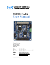
Connect Tech SSD/104 SATA User Manual
Revision 0.00
10
Power Sourcing Explaination
The SSD/104 SATA board powers its mSATA modules from +3.3V. This voltage rail can be provided
from the PCI-104 bus +3.3V rail, the PCIe/104 bus +3.3V rail or from the external +3.3V power connector
on the board. It is important to check whether your SBC or SBC’s power supply provides +3.3V over the
embedded buses, if the SBC does NOT provide +3.3V power over the bus connectors the external power
connector MUST be used.
The SSD/104 SATA board also has Ferrite Beads located near each power source that can be populated or
de-populated to select the sourcing from a particular voltage rail, in most cases the default configuration of
all installed will be adequate. These ferrites have the following designators L2, L3, and L4.
Hardware Installation Information
Please follow these steps with installing the SSD/104 SATA into your system.
1) Ensure your SBC is powered OFF
2) Install the SSD/104 SATA card onto your PC/104 stack (if available)
3) Install mSATA modules into mSATA slots on carrier
4) Connect SATA cables from SSD/104 Carrier to SBC
5) Power ON your SBC
mSATA SSD Module Information
Connect Tech’s SSD/104 SATA Carrier board allows for the installation of 2 mSATA SSD Modules.
mSATA modules should be JEDEC MO-300B compatible pinout and size. mSATA SSD modules are not
only small in size and rugged but extremely and can drastically reduce boot time.
Both SLC and MLC flash types can be used as well as commercial and industrial operating temperature
grades.
mSATA is a relatively new format for ultra-small Solid-State Disks (SSDs), developed by Intel. mSATA
SSDs take a form factor similar to mini-PCI Express cards, and is now adopted by many manufactures, see
below for a current listing of popular vendors with mSATA SSD modules available.
Listing of mSATA SSD Module Vendors
ADATA
AMP Inc.
Apacer
Delkin
Delkin
innodisk
Intel
Kingston
NetList
OCZ
Renice
RunCore
Samsung
Super Talent
Swissbit
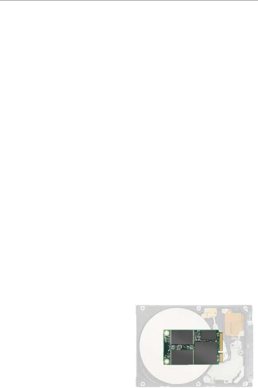
mSATA size comparison


