


Ver.1.00
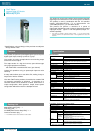
DIO-4/4(FIT)GY 3
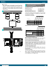
How to Connect an Interface Connector
When connecting the Module to an external device, you can
use the supplied connector plug.
To wire the Module, strip the sheath about 9 - 10mm from an
end of the wire and insert the exposed wire into an opening.
Tighten the screw to fasten the inserted wire. Applicable
wires are AWG28 - 16.
- Applicable wire:
3.81mm pitch, 12-pin type, 8.0A rated current
MC1, 5/12-GF-3.81 [made by Phoenix Contact Corp.]
- Applicable plug:
Front screw type with connector stopper flange
FRONT-MC 1,5/12-STF-3,81 [made by Phoenix Contact Corp.]
Applicable cable: AWG28-16
Turn the screw to fasten the wire.
9 - 10mm
DI-8
Device
ID
COM 0
NC
X
COM1
NC
0
3
1
2
6
5
4
7
4567
X
0123
0
4
0
4
6
2
5
1
3
7
CAUTION
Removing the connector plug by grasping the cable can
break the wire.
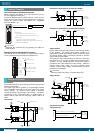
Signal Layout on the Interface Connector
The Module can be connected to an external device using a
12-pin connector that is provided on the Module face.
COM 0 --- +/-COM
N.C.
X 0 --- IN 0
X 1 --- IN 1
X 2 --- IN 2
X 3 --- IN 3
Y 0 --- OUT 0
COM 1 --- +COM
COM 2 --- -COM
Y 1 --- OUT 1
Y 2 --- OUT 2
Y 3 --- OUT 3
Input port
plus / minus common
Output port minus common
Digital Input: 4points
Digital Output: 4points
Output port plus common
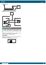
Input section
Figure below shows the input equivalent circuit for the interface
section of this product.
The signal input section consists of an Optocoupler isolated
input (compatible with both current sink output and current
source output). An external power supply is therefore
required to drive the input section of this module. The power
requirement for the <DIO-4/4(FIT)GY> or <DI-8(FIT)GY> is
about 8 mA per input channel at 24 VDC (about 4 mA at 12
VDC).
Input Circuit
Vcc
3kΩ
3k
Ω
External circuitModule
Optocoupler
Input
pin
Input
pin
+/-
common
Input contact
point
Input contact
point
12V - 24VDC
External
power supply
Optocoupler
Example of a Connection to Current Sink Output
3k
Ω
Vcc
Current sink
output
Optocoupler
Input
pin
Minus
common
12V - 24VDC
External
power supply
External circuitModule
Example of a Connection to Current Source Output
Minus
common
3k
Ω
External circuitModule
Optocoupler
Input
pin
Current
source output
External
power supply
Vcc
Output section
Figure below shows the output circuit for the interface section
of this product. The signal output section consists of an
Optocoupler isolated open collector output (current sink type).
An external power supply is therefore required to drive the
output section of this module.
The maximum output current rating per channel is 150 mA for
this product (at 12 - 24 VDC) or 50mA for this product (at 36 -
48 VDC). A surge voltage protection circuit (zener diode) is
provided for the output transistors of this module. When the
module drives relays, lamps, and other induction loads,
however, another surge voltage countermeasure should be
provided on the load side.
CAUTION
When the power is turned on, all output will be OFF.
Output Circuit
Vcc
Vcc
Plus
common
Minus
common
Output
pin
Output
pin
Optocoupler
External circuitModule
Load
Load
12V - 48VDC
External
power supply
Connection example:
Using Inputs X0
+
Input plus common (e.g., connector COM0)
Module side
Input pin (e.g., connector X0)
External
power supply
12V - 24VDC
-
Interface Connector
External I/O Circuits