


AD12-16(PCI)EVer.3.10
5
Analog Input Connection
T he input form o f analog si gnal has a single and input , and different ial input , and t he co nnect ion met hods wit h a signal differ,
respect ively . He re, t he example in t h e case of connect ing using a f lat cable o r a shield cable is shown.
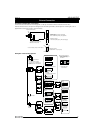
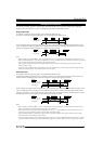
Single-ended Input
It is examp le of connect io n when usin g cables, such as optional flat cable (PC A37P).
T he source of a signal and a ground a re connect ed t o 1 t o 1 t o each a nalog input channel o f CN1.
Analog Input 0 ..1 5
Analog Ground
BOARD CN1 Cable Signal Source
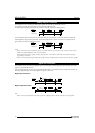
It is t he exampl e of connect ion which used shiel d cables, such as an opt ional c oaxial cabl e (PCC16PS). When t he dist ance of t he
source of a sign al and a b oard is long, please use it t o enlarge noise-p roof nat ure. T o each analo g input channel of C N1, wire l ine is
connected to signal line and the group edited by the shield is connected to a ground.
Analog Ground
Shield cable
Analog Input 0 ..1 5
BOARD CN1 Signal Source
Notes!
- When a frequency ingredient 1MHz or more is contained in the source of signal, the cross talk between channels may occur.
- When a board and the source of a signal are influenced of a noise, or when the distance of a board and the source of a signal is
long, it may be unable to input in exact data by the connection method.
- Analog signal to input must not exceed the maximum input voltage on the basis of the analog ground of a board. It may
damage, when it exceeds.
- Conversion data is unknown when input terminal is not connected. Please connect with analog ground too hastily the input
terminal of a channel which is not connected to the source of a signal.
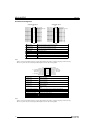
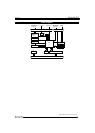
Differential Input
It is example of connectio n when usin g cables, such as optional flat cable (PC A37P).
[+] input of each analog input channel of CN1 is connect ed t o a signal, and [-] input is connect ed t o t he ground o f t he sourc e of a
signal. Furthermore, the analog ground of a board and the ground of the source of a signal are connected.
Analog Input 0[ +] ..7 [+]
Analog Ground
BOARD
Cable Signal Source
Analog Input 0[ -]. .7[ -]
CN1
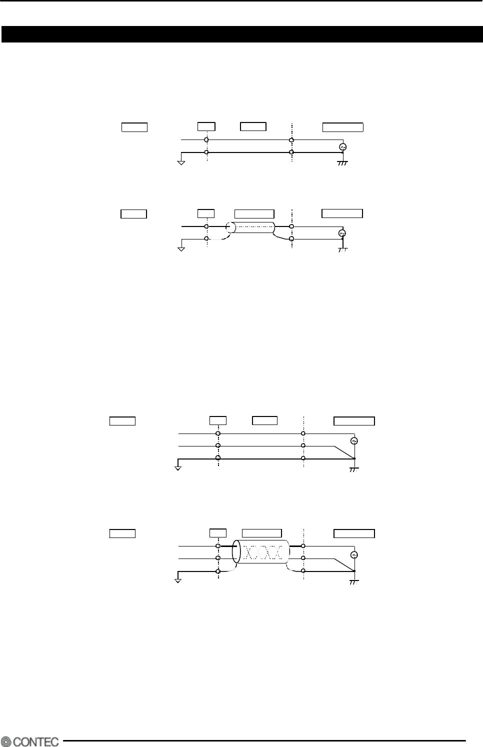
It is t he examp le of connec t ion which used shield cables, su ch as optional 2 hear t shield ca ble (PCD8PS). When t h e dist ance of t he
source of a signal and a b oard is long, please use it t o enlarge no ise-p roof nat ure. [+ ] input of each anal og input c hannel of CN1 is
connected t o a s ignal, and [-] input is connect ed t o t he ground of t he sourc e of a signal. Furt h ermore, t h e analog ground of a board
and the ground of the source of a signal are connected in the group edited by the shield.
Analog Input 0[ +] ..7 [+]
Analog Ground
BOARD
Signal Source
Analog Input 0[ -]. .7[ -]
CN1 Shield cable
Notes!
- When a frequency ingredient 1MHz or more is contained in the source of signal, the cross talk between channels may occur.
- Conversion data becomes unfixed when analog ground is not connected.
- When a board and the source of a signal are influenced of a noise, or when the distance of a board and the source of a
signal is long, it may be unable to input in exact data by the connection method.
- Analog signal inputted into [+] input and [-] input must not exceed the maximum input voltage on the basis of the analog
ground of a board. It may damage, when it exceeds.
- Conversion data when having not connected terminal of [+] input or [-] input is unfixed. Both should connect with an analog
ground too hastily the terminal of [+] input of the channel which does not connect with the source of a signal, and [-] input.