


TIME LIGHT
+
Test 20
151
5 10
AUTO
OFF ON
6105
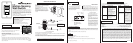
Motion Sensing
Wall Switch
The 6105 Motion Sensing Wall Switch detects motion to turn on
lights for an adjustable amount of time. A built-in photo cell can be set
to keep lights off when the lights aren't needed. The unit has excel-
lent sensitivity and a wide 150° detection range. It can be used with
incandescent lighting as well as rapid start fluorescent lighting. (Not
for use with electronic ballasts)
Installation is as easy as replacing a wall switch. However, some
codes require installation by a qualified electrician.
Features include:
• 150° motion detection angle.
• Adjustable on-time from 5 sec. to 20 min.
• Adjustable photocell.
• Works with incandescent and rapid start fluorescent lighting.
(Not for use with electronic ballasts)
• Works with motors up to 1/8 hp.
• Slide switch selectable OFF, ON AND AUTO modes.
WARNING: Turn power off at the circuit breaker before wiring.
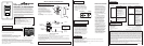
TYPICAL INSTALLATION
Control Cover
Plate Removed
MODE
Selection
Switch
• Remove the decorative coverplate (secured by two
screws).
• Remove Control Cover. (Press in with screwdriver.
Swing out cover to remove.)
• Remove the existing switch (if this is a retrofit
application).
• Connect the detector as shown in the diagram.
Before installing the detector into the box, make
sure there is no wire exposed at the connection.
• Do not connect to neutral wire or damage to unit
will occur.
If you have a problem with your Wall Switch, first follow this guide. If the problem persists, call the
customer service hotline at 1-866-853-4293 between 8:00 AM and 7:00 PM ET weekdays.
Electrical input................................................................................................................................120V, 60 Hz
Fluorescent Load (Not for electronic ballasts)....................(2) 30 Watt minimum 400 Watt maximum Rapid Start
Motor Load.............................................................................................................................1/8 HP maximum
Incandescent.........................................................................................................................500W at 120V AC
On-Time..........................................................................................Adjustable approximately 5 sec. to 20 min.
Photocell Sensor.......................................................................................From dull daylight to less than 1 FC.
Coverage...............................................................................up to 15 ft. at 150°, up to 30 ft. in front of the sensor
There are 6 preset selections for the amount
of time the lights stay on: Test (5 seconds),
1, 5, 10, 15, and 20 minutes. Use a small,
phillips screw driver to adjust the TIME
control. Turn the TIME control until it “snaps”
into the desired time position.
Replace control panel cover and install the decorative wall plate. In installations where the Cooper motion
sensor switch is combined with other switches or outlets on an expanded box, a combination wall plate will
need to be purchased. Various combination wall plates are available at Home Centers and Electrical Supply
Stores.
Slide the switch a couple of times to make sure it operates freely.
When the light in the room is at the
level you want the lights to turn on,
set the switch to the AUTO position.
Put the TIME control to the 5 sec-
ond position.
Put the LIGHT control to the mini-
mum dark (fully counter-clockwise)
position. Wait for the lights to turn
off.
Turn the LIGHT adjustment clock-
wise in very small steps and wait 2
seconds before moving your hand in
front of the sensor. Repeat until the
lights controlled by the sensor come
on. The light will now come on when
the light level is at or below the pres-
ent level and motion is detected.
To adjust the photocell:
MODE Selection Switch
Moving the switch selects one of three modes of operation: OFF, AUTO, ON
OFF: Lights stay off.
AUTO: Lights come on for time set when motion is detected and the light level is below the set level.
ON: Lights stay on continuously.
•
•
•
•
•
•
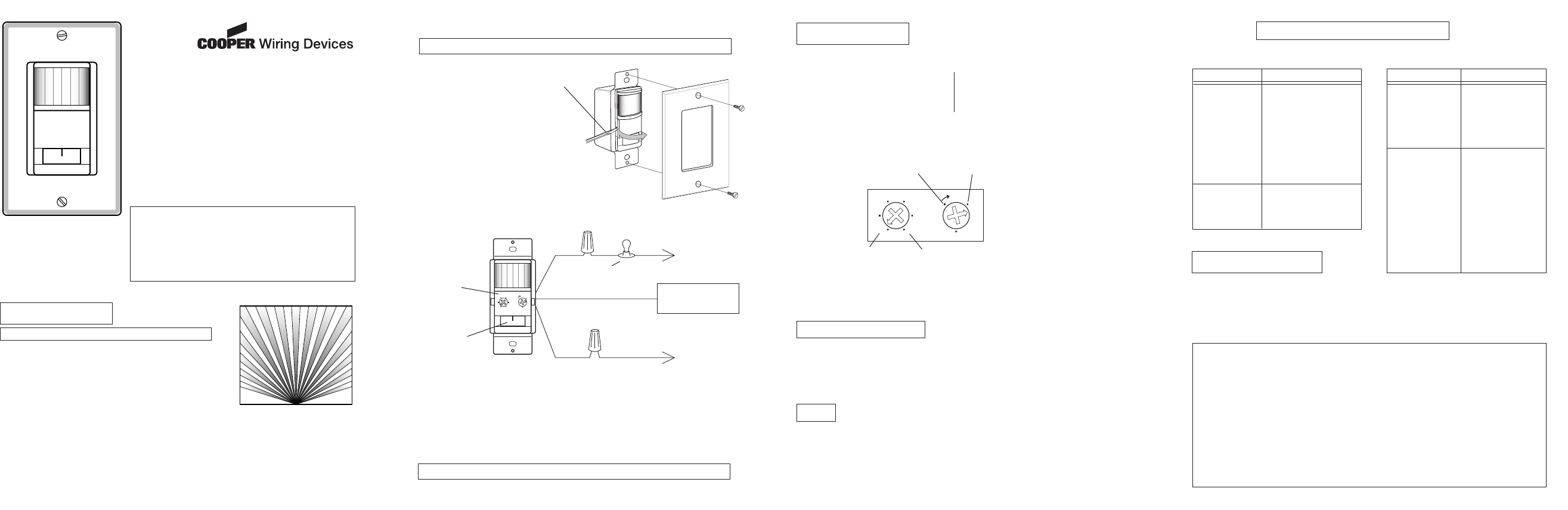
The sensor can be prevented from turning on lights
when there is already enough light in the room. Use
a small screw driver to set the light level using this
diagram as a guide. In the fully clockwise position,
the sensor turns on lights even in full daylight. In the
fully counter-clockwise poition, the sensor only turns
on lights when the surrounding light level is very low.
ADJUSTMENTS
SPECIFICATIONS
TROUBLESHOOTING
USE
TIME
Complete Installation
LIGHT LEVEL
O
FF
O
N
AU
TO
- 2 - - 3 - - 4 -
• Mount the detector into the wall box with the mounting screws.
• For test purposes, use a small screwdriver to turn the time control to TEST and the light control fully clockwise.
Turn the power back on at the circuit breaker.
• Set the switch to the AUTO mode. When unit stabilizes (about 1 minute) the sensor is ready to detect motion. If
motion is detected, the lights will turn on. The lights will turn off 5 seconds after motion is no longer detected.
(NEUTRAL)
Green ground wire to
junction box screw or
grounding wire.
BLACK
LOAD
HOT
(LINE)
TIME LIGHT
+
Test 20
151
5 10
5 Seconds
20 Minutes
Any Light
Level
Dark (low
light level)
SYMPTOM
Light does not come
on.
Lights do not stay
on in the Auto mode.
POSSIBLE CAUSE
Circuit breaker or fuse is
turned off.
If the lamp being con-
trolled has another switch,
it may be turned off.
Bulb is defective.
LIGHT control is set too
far toward the DARK posi-
tion. MODE switch is set
to OFF instead of AUTO.
Poor connection.
Motion has stopped in the
room.
TIME control is set for too
short a delay.
1.
2.
3.
4.
5.
6.
1.
2.
SYMPTOM
Light does not
turn off.
Light comes on for
no reason in the Auto
mode.
POSSIBLE CAUSE
Incorrect wiring.
MODE switch is set to
ON instead of AUTO.
Motion is still present.
Delay set by TIME
control has not
expired.
Heating or cooling ob-
jects (such as air
vents, appliances, or
drafts through the wall
box) are causing false
triggering.
Switch on the sensor
has been turned off
and back on.
There was a momen-
tary power interrup-
tion. The light will turn
off automatically when
the "on" time expires.
1.
2.
3.
4.
1.
2.
3.
YOUR COOPER WIRING DEVICES MOTION SENSOR TWO YEAR LIMITED WARRANTY
For a period of 2 years from the date of purchase, Cooper Wiring Devices will replace or repair the motion
sensing switch provided that it has not been subject to abuse, improper installation or improper use, and
is returned prepaid Cooper Wiring Devices Quality Control Department at 203 Cooper Circle, Peachtree
City, GA 30269. If the product has been discontinued, replacement will be made with the nearest available
equivalent model. This warranty does not cover consumables (such as fuses). Proof of purchase in the
form of a bill of sale or receipted invoice that shows that the item is within the applicable warranty period
must be presented to obtain the repair or replacement provided by the warranty. Repair or replacement as
provided under this warranty is the exclusive remedy of the customer. Cooper Wiring Devices shall not be
liable for any incidental or consequential damages for breach of any express or implied warranty on any
of its products. Except to the extent limited or prohibited by applicable law, any implied warranty of mer-
chantability or fitness for a particular purpose on this product is limited in duration to the duration of this
warranty. Some states do not allow the exclusion or limitation of incidental or consequential damages, or
allow limitations on how long an implied warranty lasts, so the above limitations may not apply to you. This
warranty gives you specific legal rights and you may also have other rights which vary from state to state.
LIGHTING
LOAD
GENERAL APPLICATION INFORMATION
The detector is more sensitive to motion across the front of the sensor than to motion towards the sensor.
The detector senses heat in motion and possible heat sources that change temperature quickly. Therefore, to
avoid false triggering, avoid placing the sensor where it will be aimed at air conditioners, heaters, and other
sources of heat or cold.
NEW APPLICATION
Choose a location where the motion sensor has a clear view of
the entire area where occupant motion may occur.
RETROFIT APPLICATION
Motion sensing switch will replace existing wall switch. Use only
where the existing switch location provides a clear view of the
occupied area.
Included are: • The sensor switch • Cover plate • 3 wire connectors • 2 large screws • 2 small screws.
INSTALLATION
INSTALLING THE SWITCH
SELECT A LOCATION
Typical Plan View of Coverage
30'
15'
0'
WARNING: For indoor use only.
Questions? Call 1-866-853-4293 8:00 AM to 7:00 PM Eastern Time, weekdays
469MV-PT
Note: Adjusting screws
found under (Off-Auto-On)
face plate.
BLACK
598-1177-03 E