


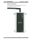
InfiNET EX™ Gateway Crestron CEN-RFGW-EX
Connectors, Controls & Indicators (Continued)
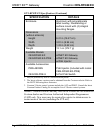
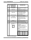
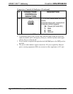
# CONNECTORS
1
,
CONTROLS &
INDICATORS
DESCRIPTION
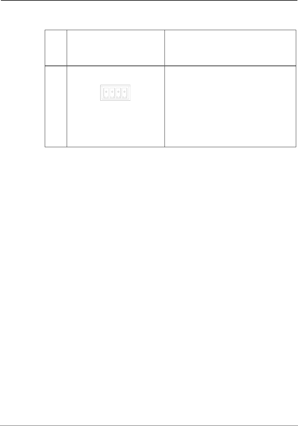
8 NET
3
GZY
24
(1) 3.5 mm detachable terminal
block;
Cresnet slave port, connects to
Cresnet control network
24: Power (24 Volts DC)
Y: Data
Z: Data
G: Ground
1. Interface connector for NET port is provided with the unit.
2. To determine which is pin 1 on the cable, hold the cable so that the end of the
eight pin modular jack is facing away from you, with the clip down and copper
side up. Pin 1 is on the far left.
3. Power should be supplied through either the LAN PoE port or the NET port but
not both.
4. The pin out table indicates signal connections. DC power applied by Ethernet
power sourcing equipment (PSE) can connect to either signal pins or N/C pins.
8 • infiNET EX™ Gateway: CEN-RFGW-EX Operations & Installation Guide – DOC. 6706A