


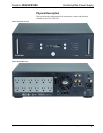
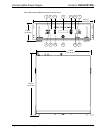
Crestron CEN-UPS1250 Uninterruptible Power Supply
Connectors, Controls & Indicators (Continued)
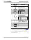
# CONNECTORS,
CONTROLS &
INDICATORS
DESCRIPTION
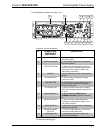
21
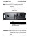
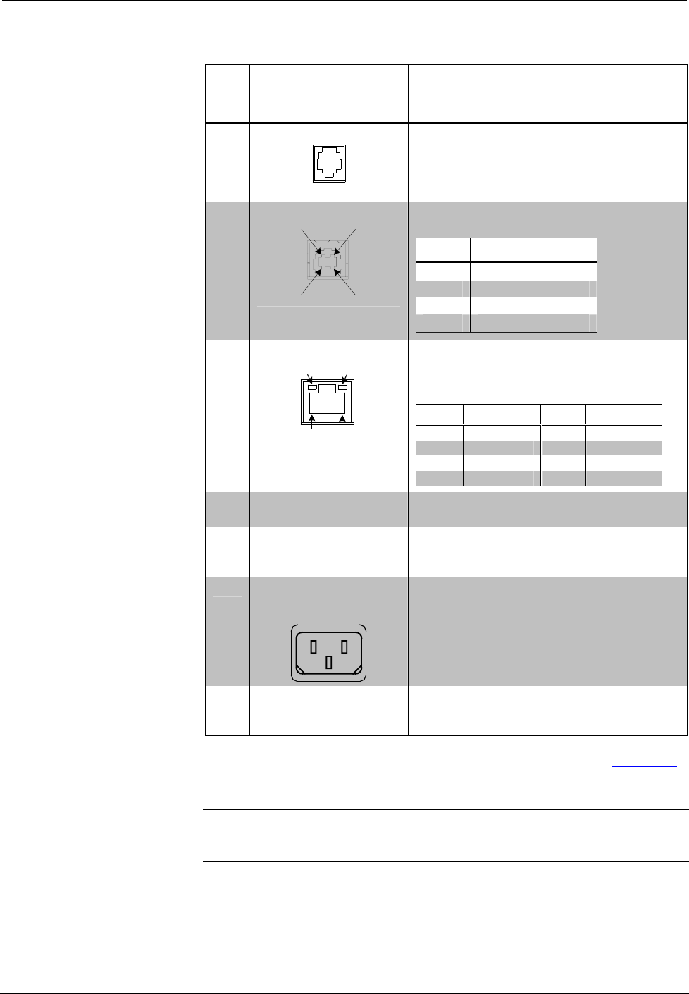
TELCO
IN – (1) 4-pin RJ-11 female;
Dual line telephone connection.
OUT – (2) 4-pin RJ-11 female;
Protected dual line telephone/modem device
connection.
22
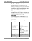
COMPUTER
Pin 2 Pin 1
Pin 3 Pin 4
(1) USB Type B female;
USB computer console port (cable included).
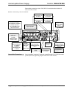
PIN DESCRIPTION
1 +5 VDC
2 Data -
3 Data +
4 Ground
23
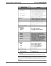
LAN
3
GREEN
LED
YELLOW
LED
PIN 8
PIN 1
(1) 8-wire RJ-45 with two LED indicators;
10/100BaseT Ethernet port;
Green LED indicates link status;
Yellow LED indicates Ethernet activity.
PIN SIGNAL PIN SIGNAL
1 TX + 5 N/C
2 TX - 6 RC -
3 RC+ 7 N/C
4 N/C 8 N/C
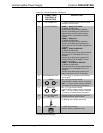
24 RESET BUTTON
(1) Red miniature pushbutton, resets
communications board.
25 ENV PROBE
6-pin mini-DIN female;
Connection for external temperature/RH
sensor (included).
26
INPUT 120V
47-63 Hz 12A
(MAIN POWER INPUT)
(1) IEC-320 C14 chassis plug;
Line power input, mates with 10 ft. (3.05 m)
power cord (included).
27 WIRING FAULT LED
(1 red) Indicates a missing ground,
overloaded neutral or reversed polarity at the
line power input.
1. The unit does not have to be powered on for batteries to recharge.
2. American Power Conversion Corp. (APC), W. Kingston, Rhode Island, US; Website: www.apc.com.
3. To determine which is pin 1 on the cable, hold the cable so that the end of the eight pin modular jack
is facing away from you, with the clip down and copper side up. Pin 1 is on the far left.
CAUTION: When resetting the Circuit Breaker, push the button in quickly and
release the button. Do not hold the Circuit Breaker button in. Failure to comply
may result in equipment damage.
Operations & Installation Guide – DOC. 6635A Uninterruptible Power Supply: CEN-UPS1250 • 9