


Interface Module Crestron TPS-IMPC
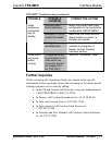
AUDIO INPUT Pinouts
PIN DESCRIPTION
S Shield
R + Right Positive
R - Right Negative
L + Left Positive
L- Left Negative
S Shield
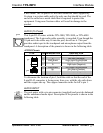
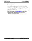
MIC OUT
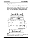
The port mates with a three-pin connector (supplied) and produces line
level differential output. Description of the pinouts is shown in the
following table.
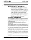
MIC OUT Pinouts
PIN DESCRIPTION
+ Positive
- Negative
S Shield
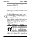
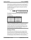
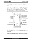
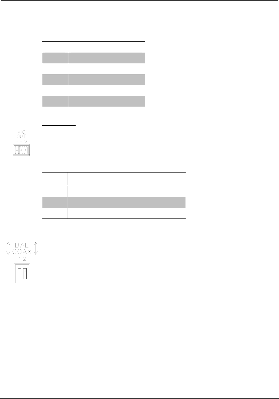
BAL/COAX
While not a port, these DIP switches are used to select which video
connections (balanced or unbalanced) to use when receiving video
signals. When used with a TPS-VID-2, each composite video signal can
come in on either the twisted pair (balanced) or coaxial (unbalanced)
connector. When used with a TPS-VID-1, the video signal (S-video or
composite) can be received over the twisted pair (balanced) or coaxial
(unbalanced) connectors. As long as a switch is in the appropriate
position, a signal can be connected to either the BNC or twisted-pair
connector.
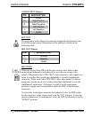
To select the twisted pair connector for balanced video, the DIP switch
for the respective video source must be in the “UP” position. To use the
coaxial connector(s) for unbalanced video, the DIP switch must be in the
“DOWN” position.
6 • Interface Module: TPS-IMPC Operations Guide - DOC. 6162