


Crestron TPS-IMPC Interface Module
Industry Compliance
As of the date of manufacture, the TPS-IMPC has been tested and found
to comply with specifications for CE marking and standards per EMC
and Radiocommunications Compliance Labelling (N11785).
Setup
Network Wiring
CAUTION: Use only Crestron power supplies for Crestron equipment.
Failure to do so could cause equipment damage or void the Crestron
warranty.
CAUTION: Possible equipment damage if miswired.
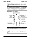
NOTE: When installing network wiring, refer to the latest revision of the
wiring diagram(s) appropriate to your specific system configuration,
available from the Downloads | Product Manuals | Wiring Diagrams
section of the Crestron website (www.crestron.com).
NOTE: Do not power up system until all wiring is verified. Care should
be taken to ensure data (Y, Z) and power (24, G) connections are not
crossed.
NOTE: All network wiring must consist of two twisted-pairs. One
twisted pair is the +24V conductor and the GND conductor and the other
twisted pair is the Y conductor and the Z conductor.
NOTE: For larger networks (i.e., greater than 28 network devices), it
may be necessary to add a Cresnet Hub/Repeater (CNXHUB) to maintain
signal quality throughout the network. Also, for networks with lengthy
cable runs or varying types of network devices, it may be desirable to add
a hub/repeater after only 20 network devices.
When calculating the wire gauge for a particular network run, the length
of the run and the power factor of each network unit to be connected
Operations Guide - DOC. 6162 Interface Module: TPS-IMPC • 7