Installing and Using the 4-Port PoweredUSB Hub
Connections
Operations Guide 930232A CyberData Corporation
7
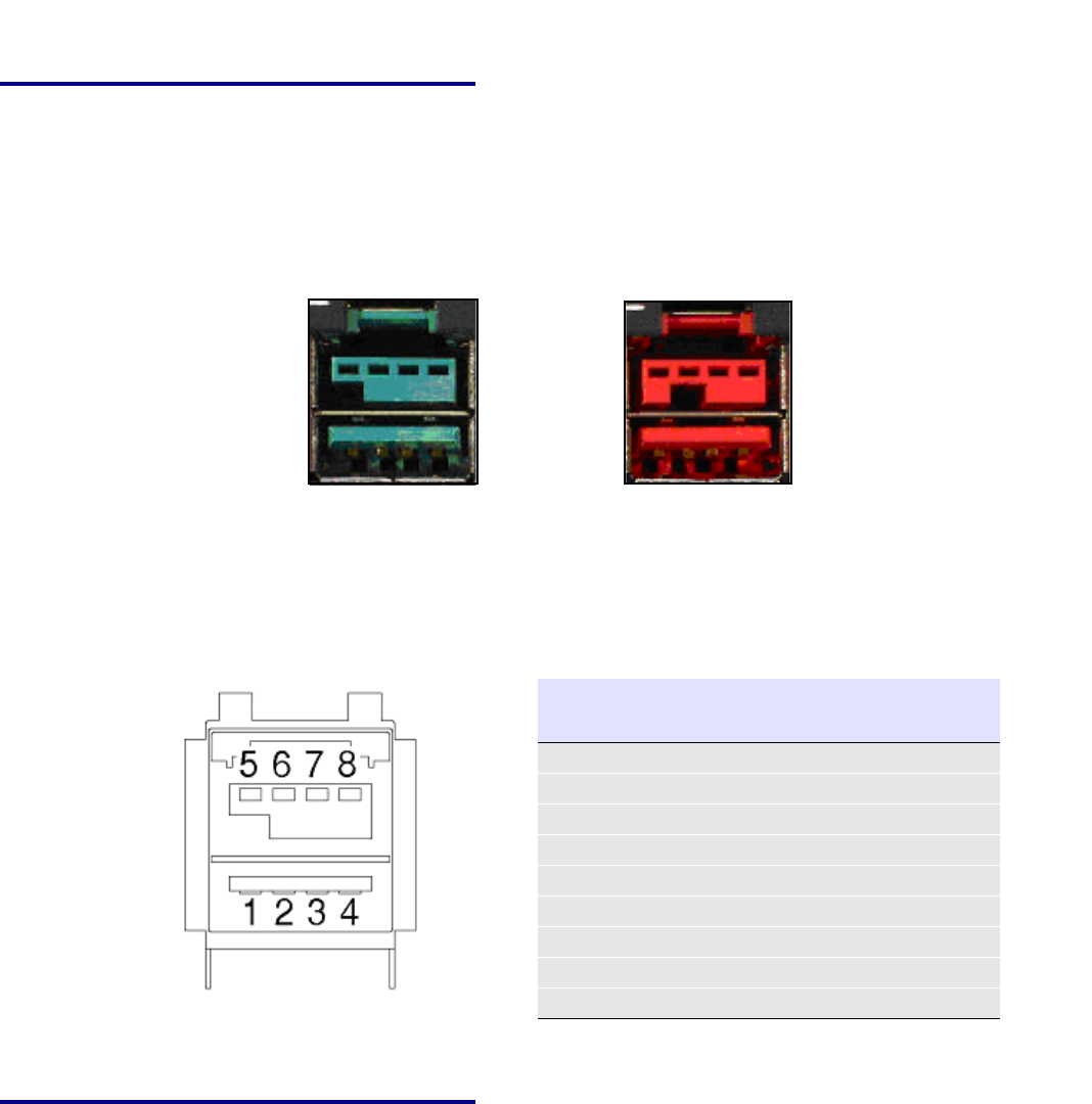
2.4.4 Connector Color Keys
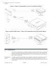
The PoweredUSB connectors are color keyed so that only the correct voltage cables can be installed.
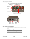
Figure 2-7. Color-Coding for Connectors
Figure 2-8. USB PoweredUSB Socket Connector Pin Assignments
2.4.5 Peripherals Connections to the SiP VoIP and PoE Speaker
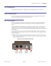
This figure illustrates the cable routing from the SiP VoIP and PoE Speaker to the Dell Retail
Integrator.
Teal Red
12 Volt Keyed
1.5A each
Ports 1,2, and 3
12 Volt Keyed
1.5A each
Ports 1,2, and 3
PIN OUT
Pin Signal Description
1 Vbus USB standard “A”
2 D- USB standard “A”
3 D+ USB standard “A”
4 Ground USB standard “A”
5 Ground USB PlusPower
6 Vplus USB PlusPower
7 Vplus USB PlusPower
8 Ground USB PlusPower
Shell Shield


