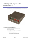
Installing and Using the 4-Port PoweredUSB Hub
Installation
Operations Guide 930232A CyberData Corporation
5
2.3 Installation
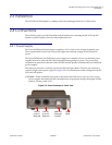
The SiP VoIP and PoE Speaker is a tabletop unit with mounting feet that sit on a flat surface.
2.4 Connections
This following topics provide illustrations and information on connecting the SiP VoIP and PoE
Speaker to power supplies, the host, and peripheral devices.
2.4.1 Power Supply
The PoweredUSB specification requires supplying +12V at 1.5A to each voltage designated port.
These requirements are met only if the power supply has sufficient wattage for this amount of
power.
The Epson PS180 brick and Dell printer power supply are examples
of lower-cost alternate power
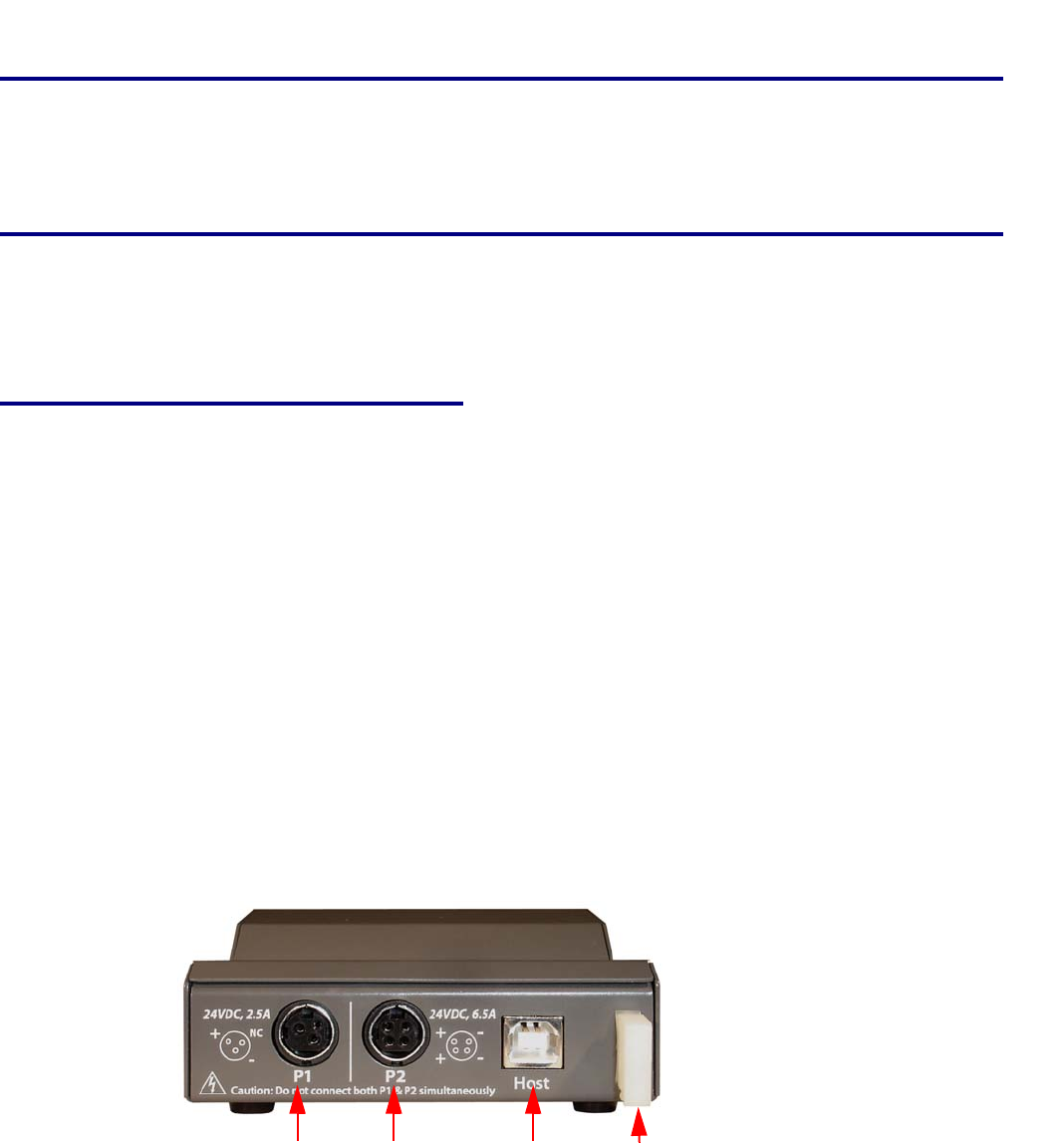
supplies that can be used with this Hub and peripherals requiring less power. Two power plug
receptacles are provided on the back of the SiP VoIP and PoE Speaker to facilitate the use of alternate
power supplies.
The three-pin connector is normally used for the Dell and Epson
Bricks. The four-pin connector is
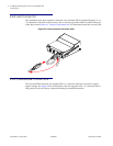
used for a high-current power supply. See Figure 2-9 for an illustration of cable routing fr
om the SiP
VoIP and PoE Speaker.
CAUTION The P1 and P2 DC
input jacks on the back of this Hub are for input only. Do not plug
power supplies into both input jacks simultaneously as equipment damage that might void the
product warranty could occur.
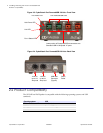
Figure 2-5. Power Connectors—Back View
+24V for
up to 2.5
Amp load
+24V for
up to 6.5
Amp load
USB Host
Connector
(Type B)
Strain
Relief


