


CPS1250AVR
Guaranteed Uninterruptible Power System
DESCRIPTION
INSPECTION
The box should contain the following:
(1) PowerPanel Plus™ software (floppy disk); (1) serial interface cable (DB-9); (1) telephone communication cable; (1) user manual; (1) warranty registration
card; (1) UPS unit.
HOW TO DETERMINE THE POWER REQUIREMENTS OF YOUR EQUIPMENT
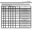
1. Make sure that the total Volt-Amp (VA) requirements of your computer, monitor and peripheral equipment does not exceed 1440VA.
2. Insure that the equipment plugged into the three battery power-supplied outlets does not exceed the UPS unit’s rated capacity (1250VA/670W for
CPS1250AVR). If rated unit capacities are exceeded, an overload condition may occur and cause the UPS unit to shut down or the circuit breaker
to trip.
3. If the power requirements of your equipment are listed in units other than Volt-Amps (VA), convert Watts (W) or Amps (A) into VA by doing the
calculations below. Note: The below equation only calculates the maximum amount of VA that the equipment can use, not what is typically used
by the equipment at any one time. Users should expect usage requirements to be approximately 60% of below value.
TO ESTIMATE POWER REQUIREMENTS:
Watts (W) x 1.82 = VA or Amps (A) x 120 = VA
Add the totals up for all pieces of equipment and multiply this total by .6 to calculate actual requirements.
There are many factors that can affect the amount of power that your computer system will require. The total load that you will be placing on the
battery-powered outlets should not exceed 80% of the unit’s capacity.
1
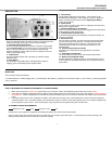
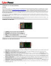
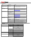
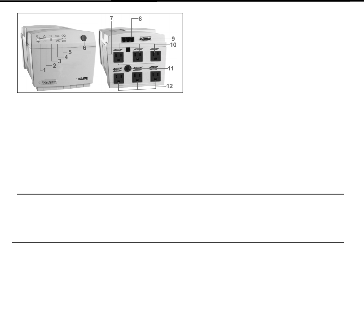
1. Power on Indicator
This LED is illuminated when the utility condition is normal and the UPS
outlets are providing “clean power”, free of surges and spikes
2.
Electrical Wiring Fault Indicator
This LED indicator will illuminate to warn the user that a wiring problem
exits with
the AC outlet
, such as bad ground, miss ground or reversed
wiring. If this is illuminated, the user is advised to disconnect all
electrical equipment from the outlet and have an electrician check the
outlet to insure proper wiring.
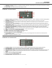
3.
AVR Indicator
This LED indicates that the UPS is operating in automatic voltage
regulation mode.
4. Using Battery
This illuminates during utility failure, indicating that the battery is
supplying power to the battery-power supplied outlets.
5. Check Battery
This illuminates indicating a weak battery. If the indicator is still
illuminated after allowing the unit to charge for 12 hours, replace the
battery according to the instructions in the
Replacing the Battery
section of this manual.
6. Power Switch
Can be used as a master on/off switch for equipment connected to the
battery power supplied outlets.
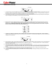
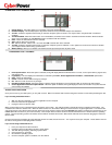
7.
All outlets Designed for AC Adapters
Allows six AC power adapter blocks to be plugged into the UPS without
making adjacent outlets inaccessible.
8. Communication Protection Ports
Communication protection ports will protect any standard modem, fax
machine or telephone.
9. Serial Port to PC
This port allows connection and communication from the DB-9 serial
port on the computer to the UPS unit. The UPS communicates its
status to the PowerPanel Plus™ software. This interface is also
compatible with the UPS service provided by Windows NT and
Windows 2000.
10. Full-time Surge Protection Outlets
All outlets on the unit provide surge suppression for connected
equipment.
11. Re-settable Circuit Breaker
The circuit breaker provides circuit overload and fault protection.
12. Battery Power Supplied Outlets
Provides three battery-supplied outlets for connected equipment and
insures temporary uninterrupted operation of your equipment during a
power failure.