


4.1 PINOUT
The COML 2232F is supplied with a 12” Y-cable that terminates with two DB-9M connectors
with female jackscrews (to match the port at the back of a PC). The pinout below applies to the
DB-9M connectors on the supplied cable. “Port1” and “Port2” is marked on the cables.
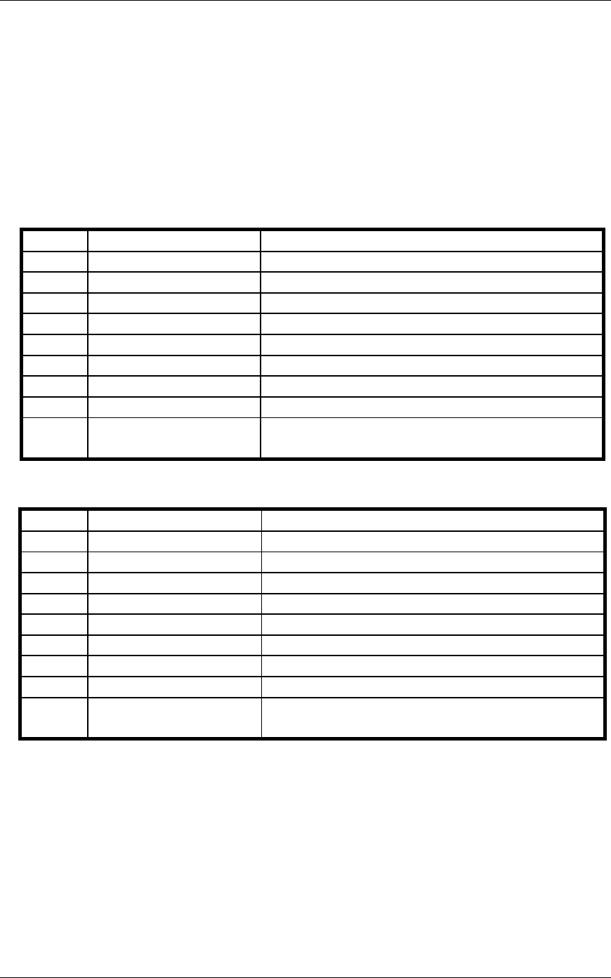
PORT1
PIN NAME FUNCTION
1 -
-
2 RX1 Receive Data input 1
3 TX1 Transmit Data output 1
4 - -
5 ISOGND ISOLATED GROUND
6 - -
7 RTS1 Request To Send output 1
8 CTS1 Clear To Send input 1
9 - -
Shell - See note*
PORT2
PIN NAME FUNCTION
1 -
-
2 RX2 Receive Data input 2
3 TX2 Transmit Data output 2
4 - -
5 ISOGND ISOLATED GROUND
6 - -
7 RTS2 Request To Send output 2
8 CTS2 Clear To Send input 2
9 - -
Shell - See note*
* The cable shield is grounded at the card-end, runs the full length of the cable and is not connected at the equipment
end (i.e., does not connect to the DB-9 shell) to help to avoid ground loops.
Technical Note: Please terminate any control signals that are not going to be used. The most common way to do
this is connect RTS to CTS. Terminating these pins, if not used, will help insure you get the best performance from
your adapter.
COML 2232F CyberResearch
®
Serial Communications
4 ©Copyright 2006 CyberResearch, Inc.
Hardware Specification