


HARDWARE
CPCI-824 User’s Manual 2-7
Revision 1.0, January 2006
2.8 PERIPHERAL BUS
The CPCI-824 utilizes the 440GX External Bus Controller (EBC) as a data communication path to the
Flash memory and other peripheral devices such as LEDs and the CPLD for the external register
control. The address/data path is on a programmable 8-bit width bus and operates at high bandwidth.
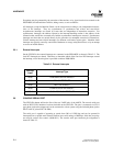
2.8.1 Flash ROM
The CPCI-824 provides 8 Mbytes of sector-programmable Flash ROM for non-volatile code storage.
The CPCI-824 Flash ROM is an Intel Strataflash J3 type-device, 8 (28F640J3) MBytes in size. The
width of the flash bus is 8 bits.
On the CPCI-824, the Flash ROM is mapped beginning at address FF80 0000h, and is divided into four
separate memory regions by Breeze firmware: boot region, flash file system, free flash, and boot
parameter region. The mapping ensures that, after a reset, the processor can begin execution at the reset,
the processor can begin execution at the reset vector address FFFF FFFCh. The size and start location
of each of these regions is defined by Breeze software. Refer to the Breeze for 440GX Developer’s
Manual for more information.
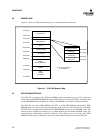
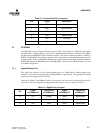
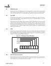
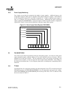
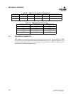
2.8.2 LEDS
The CPCI-824 front panel has four green LEDs. The four green LEDs labeled IOP, ACT, STAT0, and
STAT1 are under software control. The LEDs are controlled by a write-only register which is located at
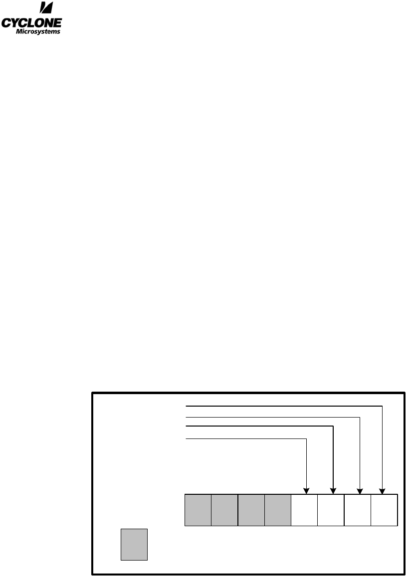
address E000 0001H. The LED Register bitmap is shown in Figure 2-2. A given LED is turned ON by
writing a “1” to the appropriate bit in the LED register.
Figure 2-2. LED Register Bitmap, E800 0001H
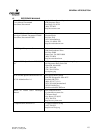
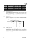
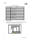
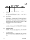
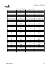
2.8.3 User LEDs During Initialization
Breeze indicates the progress of its hardware initialization on the user LEDS. In the event that initial-
ization should fail for some reason, the number of lit LEDs can be used to determine the cause of
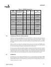
failure. Table 2-6 lists the tests that correspond to each LED.
01
3
24567
Reserved
STAT0
Activity
STA1
IOP
(write only)
(1) LED on
(0) LED off