CY7C145, CY7C144
Document #: 38-06034 Rev. *D Page 8 of 21
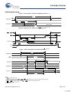
Switching Waveforms
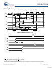
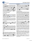
Figure 5. Read Cycle No. 1 (Either Port Address Access)
[15, 16]
Figure 6. Read Cycle No. 2 (Either Port CE/OE Access)
[15, 17, 18]
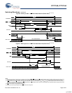
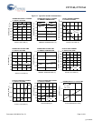
Figure 7. Read Timing with Port-to-Port Delay (M/S=L)
[19, 20]
Notes
15.R/W
is HIGH for read cycle.
16.Device is continuously selected CE
= LOW and OE = LOW. This waveform cannot be used for semaphore reads.
17.Address valid prior to or coincident with CE
transition LOW.
18.CE
L
= L, SEM = H when accessing RAM. CE = H, SEM = L when accessing semaphores.
19.BUSY
= HIGH for the writing port.
20.CE
L
= CE
R
= LOW.
t
RC
t
AA
t
OHA
DATA VALIDPREVIOUS DATA VALID
DATA OUT
ADDRESS
t
ACE
t
LZOE
t
DOE
t
HZOE
t
HZCE
DATA VALID
DATA OUT
SEM
or CE
OE
t
LZCE
t
PU
I
CC
I
SB
t
PD
VALID
t
DDD
t
WDD
MATCH
MATCH
R/W
R
DATAIN
R
DATA
OUTL
t
WC
ADDRESS
R
t
PWE
VALID
t
SD
t
HD
ADDRESS
L
[+] Feedback


