CY7C68300C/CY7C68301C
CY7C68320C/CY7C68321C
Document 001-05809 Rev. *A Page 13 of 42
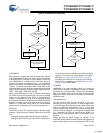
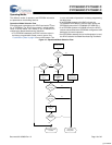
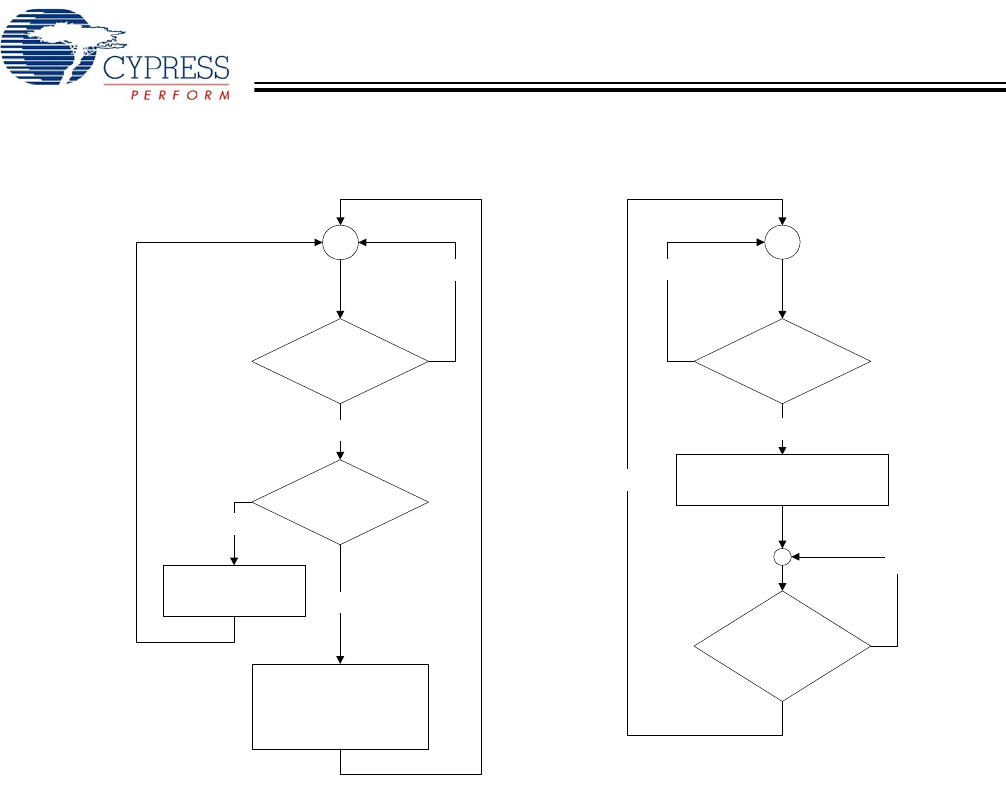
Figure 8. SYSIRQ Latching Algorithm
DRVPWRVLD
When this pin is enabled with bit 0 of configuration address
0x08 (DRVPWRVLD Enable), the AT2LP informs the host that
a removable device, such as a CF card, is present. The AT2LP
uses DRVPWRVLD to detect that the removable device is
present. Pin polarity is controlled by bit 1 of configuration
address 0x08. When DRVPWRVLD is deasserted, the AT2LP
reports a “no media present” status (ASC = 0x3A, ASQ = 0x00)
when queried by the host. When the media has been detected
again, the AT2LP reports a “media changed” status to the host
(ASC = 0x28, ASQ = 0x00) when queried.
When a removable device is used, it is always considered by
the AT2LP to be the IDE master device. Only one removable
device may be attached to the AT2LP. If the system only
contains a removable device, bit 6 of configuration address
0x08 (Search ATA Bus) must be set to ‘0’ to disable ATA device
detection at startup. If a non-removable device is connected in
addition to a removable media device, the non-removable
device must be configured as IDE slave (device address 1).
GPIO Pins
The GPIO pins allow for a general purpose input and output
interface. There are several different interfaces to the GPIO
pins:
• Configuration bytes 0x09 and 0x0A contain the default
settings for the GPIO pins upon initial AT2LP configuration.
• The host can modify the settings of the GPIO pins during
operation. This is done with vendor-specific commands
described in “Programming the EEPROM” on page 33.
• The status of the GPIO pins is returned on the interrupt
endpoint (EP1) in response to a SYSIRQ. See “SYSIRQ”
on page 12 for SYSIRQ details.
LOWPWR#
LOWPWR# is an output pin that is driven to ‘0’ when the
AT2LP is not in suspend. LOWPWR# is placed in Hi-Z when
the AT2LP is in a suspend state. This pin only indicates the
state of the AT2LP and must not be used to determine the
status of the USB host because of variations in the behavior
of different hosts.
ATA Interface Pins
The ATA Interface pins must be connected to the corre-
sponding pins on an IDE connector or mass storage device.
To allow sharing of the IDE bus with other master devices, the
AT2LP can place all ATA Interface Pins in a Hi-Z state
whenever VBUS_ATA_ENABLE is not asserted. Enabling this
feature is done by setting bit 4 of configuration address 0x08
to ‘1’. Otherwise, the ATA bus is driven by the AT2LP to a
default inactive state whenever VBUS_ATA_ENABLE is not
asserted.
Design practices for signal integrity as outlined in the
ATA/ATAPI-6 specification must be followed with systems that
utilize a ribbon cable interconnect between the AT2LP’s ATA
USB Interrupt
Pipe Polled?
Yes
No
NAK Request
SYSIRQ=1?
Latch State of IO Pins
Set Int_Data = 1
Int_Data = 1?
No
Return Interrupt Data
Set Int_Data = 0
Yes
Yes
No
Yes
Int_Data = 0
and
SYSIRQ=0?
No
[+] Feedback


