CY7C68300C/CY7C68301C
CY7C68320C/CY7C68321C
Document 001-05809 Rev. *A Page 23 of 42
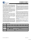
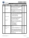
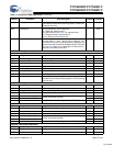
SRST Enable Bit 1
Determines if the AT2LP is to do an SRST reset during drive
initialization. At least one reset must be enabled. Do not set
SRST to 0 and Skip Pin Reset to 1 at the same time.
0 = Do not perform SRST during initialization.
1 = Perform SRST during initialization.
Skip Pin Reset Bit 0
Skip ARESET# assertion. When this bit is set, the AT2LP
bypasses ARESET# during any initialization other than
power up. Do not set SRST Enable to 0 and Skip Pin Reset
to 1 at the same time.
0 = Allow ARESET# assertion for all device resets.
1 = Disable ARESET# assertion except for chip reset cycles.
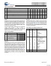
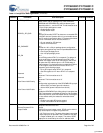
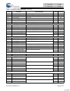
0x06 ATA UDMA Enable Bit 7
Enable Ultra DMA data transfer support for ATA devices. If
enabled, and if the ATA device reports UDMA support for the
indicated modes, the AT2LP uses UDMA data transfers at
the highest negotiated rate possible.
0 = Disable ATA device UDMA support.
1 = Enable ATA device UDMA support.
0xD4
ATAPI UDMA Enable Bit 6
Enable Ultra DMA data transfer support for ATAPI devices.
If enabled, and if the ATAPI device reports UDMA support
for the indicated modes, the AT2LP uses UDMA data
transfers at the highest negotiated rate possible.
0 = Disable ATAPI device UDMA support.
1 = Enable ATAPI device UDMA support.
UDMA Modes Bits 5:0
These bits select which UDMA modes are enabled. The
AT2LP operates in the highest enabled UDMA mode
supported by the device. The AT2LP supports UDMA modes
2, 3, and 4 only.
Bit 5 = Reserved. Must be set to 0.
Bit 4 = Enable UDMA mode 4.
Bit 3 = Enable UDMA mode 3.
Bit 2 = Enable UDMA mode 2.
Bit 1 = Reserved. Must be set to 0.
Bit 0 = Reserved. Must be set to 0.
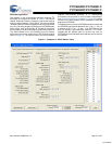
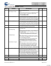
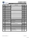
0x07 Reserved Bits 7:3
Must be set to 0.
0x07
Multi-word DMA mode Bit 2
This bit enables multi-word DMA support. If this bit is set and
the drive supports it, multi-word DMA is used.
PIO Modes Bits 1:0
These bits select which PIO modes are enabled. Setting to
‘1’ enables use of that mode with the attached drive, if the
drive supports it. Multiple bits may be set. The AT2LP
operates in the highest enabled PIO mode supported by the
device. The AT2LP supports PIO modes 0, 3, and 4 only.
PIO mode 0 is always enabled and has no corresponding
configuration bit.
Bit 1 = Enable PIO mode 4.
Bit 0 = Enable PIO mode 3.
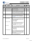
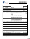
Table 11.Configuration Data Organization (continued)
Byte
Address
Configuration
Item Name
Configuration
Item Description
Required
Contents
Variable
Contents
[+] Feedback


