CY7C656x
x
PRELIMINARY
Document #: 38-08037 Rev. *D Page 5 of 23
unpowered state. Once the hubs are configured, the ports are
not driven, and the host may power the ports by sending a
SetPortPower command to each port. After a port is powered,
any connect or disconnect event is detected by the hub. Any
change in the port state is reported by the hubs back to the
host through the Status Change Endpoint (endpoint 1). Upon
receipt of SetPortReset command from the host, the hub will
• Drive SE0 on the corresponding port
• Put the port in an enabled state
• Enable the green port indicator for that port (if not previously
overridden by the host)
• Enable babble detection once the port is enabled.
Babble consists of either unterminated traffic from a
downstream port (or loss of activity), or a non-idle condition on
the port after EOF2. If babble is detected on an enabled port,
that port will be disabled. A ClearPortEnable command from
the host will also disable the specified port.
Downstream ports can be individually suspended by the host
with the SetPortSuspend command. If the hubs are not
suspended, any resume will be confined to that individual port
and reflected to the host through a port change indication in
the Hub Status Change Endpoint. If the hubs are suspended,
a resume on this port will be forwarded to the host, but other
resume events will not be seen on that port. The host may
resume the port by sending a ClearPortSuspend command.
5.5 Upstream Port
The upstream port includes the transmitter and the receiver
state machine. The Transmitter and Receiver operate in high-
speed and full-speed depending on the current hub configu-
ration.
The transmitter state machine monitors the upstream facing
port while the Hub Repeater has connectivity in the upstream
direction. This monitoring activity prevents propagation of
erroneous indications in the upstream direction. In particular,
this machine prevents babble and disconnect events on the
downstream facing ports of this hub from propagating and
causing the hub to be disabled or disconnected by the hub to
which it is attached. This allows the Hub to only disconnect the
offensive port on detecting a babble from it.
5.6 Power Switching
The CY7C656xx includes interface signals for external port
power switches. Both ganged and individual (per-port) config-
urations are supported, with individual switching being the
default. Initially all ports are unpowered. After enumerating,
the host may power each port by sending a SetPortPower
command for that port. The power switching and over-current
detection of downstream ports is managed by control pins
connected to an external power switch device. PWR [n]#
output pins of the CY7C656xx series are connected to the
respective external power switch's port power enable signals.
(Note that each port power output pin of the external power
switch must be bypassed with an electrolytic or tantalum
capacitor as required by the USB specification. These capac-
itors supply the inrush currents, which occur during
downstream device hot-attach events.) The polarity of this pin
can be configured through the EEPROM, see section 9.3.
5.7 Over-current Detection
Over-current detection includes timed detection of 8 ms by
default. This parameter is configured from the external
EEPROM in a range of 0 ms to 15 ms for both an enabled port
and a disabled port individually. Detection of over-current on
downstream ports is managed by control pins connected to an
external power switch device.
The OVR[n]# pins of the CY7C656xx series are connected to
the respective external power switch's port over-current
indication (output) signals. Upon detecting an over-current
condition, the hub device reports the over-current condition to
the host and disables the PWR# output to the external power
device. The polarity of this pin can be configured through the
EEPROM, see section 9.3.
5.8 Port Indicators
The USB 2.0 port indicators are also supported directly by the
CY7C656xx. As per the specification, each downstream port
of the hub supports an optional status indicator. The presence
of indicators for downstream facing ports is specified by bit 7
of the wHubCharacteristics field of the hub class descriptor.
The default CY7C656xx descriptor specifies that port
indicators are supported (wHubCharacteristics, bit 7 is set). If
port indicators are not included in the hub, this should be
disabled by the EEPROM.
Each port indicator is strategically located directly on the
opposite edge of the port which it is associated with. The
indicator provides two colors: green and amber. This is imple-
mented as two separate LEDs, one amber and the other
green. A combination of hardware and software control is used
to inform the user of the current status of the port or the device
attached to the port and to guide the user through problem
resolution. Colors and blinking are used to provide information
to the user. The significance of the color of the LED depend on
the operational mode of the CY7C656xx. There are two modes
of operation for the CY7C656xx port indicators: automatic and
manual.
On power-up the CY7C656xx defaults to Automatic Mode,
where the color of the Port Indicator (Green, Amber, Off)
indicates the functional status of the CY7C656xx port. In
Automatic Mode, the CY7C656xx will turn on the green LED
whenever the port is enabled and the amber LED when it has
had an overcurrent condition detected. The color of the port
indicator is set by the port state machine. Blinking of the LEDs
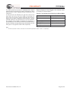
is not supported in Automatic Mode. Table 5-1 below identifies
the mapping of color to port state in Automatic Mode.
Table 5-1. Automatic Port State to Port Indicator Color Mapping
Downstream Facing Hub Port State
Powered Off
Disconnected, Disabled, Not
Configured, Resetting, Testing
Enabled, Transmit, or
TransmitR
Suspended, Resuming,
SendEOR, Restart_E /S
Off or Amber if due to an
Overcurrent Condition
Off Green Off


