


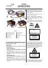
DS4600A QUICK GUIDE
3
Accessories:
Name Description Part Number
C-BOX 100/200 Connection Box 93ACC1510, 93ACC1520
C-BOX 300/310 Connection Box Profibus 93A301000, 93A301030
GFC-41 90° Reading Device 91D081000
OM4000 Oscillating Mirror 93A251030
INT-24 20 mA Current Loop Interface Board 93A151000
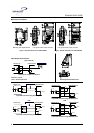
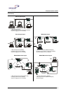
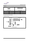
Electrical Connections:
DS4600A is equipped with a cable terminated by a 25-pin female D-sub connector for connection to the power
supply and input/output signals.
CAUTION
Do not connect GND and SGNDs (Main or Aux) to different (external) ground references.
GND and SGNDs (Main and Aux) are internally connected through filtering circuitry which
can be permanently damaged if subjected to voltage drops over 0.8 Vdc.
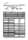
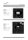
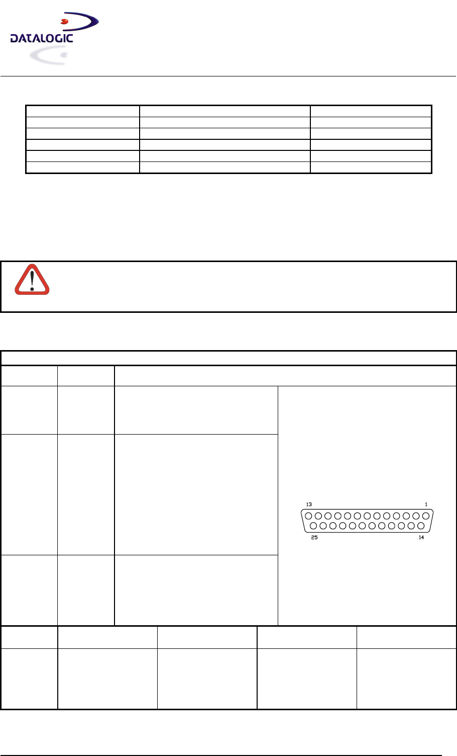
The details of the connector pins are indicated in the following table:
25-pin D-sub female connector pinout
Pin Name Function
13 VS Power supply input voltage +
25 GND Power supply input voltage -
1 CHASSIS Chassis Ground
9 VS External Trigger supply voltage +
18 EXT TRIG+ External Trigger +
19 EXT TRIG- External Trigger -
6 IN1+ Input 1 +
10 IN1- Input 1 -
14 IN2+ Input 2 +
15 IN2- Input 2 -
8 OUT1 + Output 1 +
22 OUT1- Output 1 -
11 OUT2 + Output 2 +
12 OUT2- Output 2 -
20 RXAUX Auxiliary RS232
21 TXAUX Auxiliary RS232
23 SGND Aux Signal Ground Auxiliary interface
24 GND Power Supply Voltage -
16 Reserved
17 Reserved
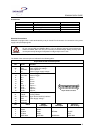
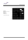
25-pin female connector
Pin RS232
RS485
Full-Duplex
RS485
Half-Duplex
20 mA C.L.
(INT-24 Only)
2 TX232 TX485+ RTX485+
3 RX232 RX485+
4 RTS232 TX485- RTX485- CLOUT-
5 CTS232 RX485- CLIN-
7 SGND Main SGND Main SGND Main SGND Main