


COMMON FEATURES
Typical Installations:
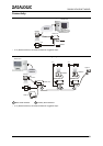
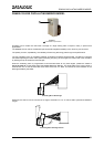
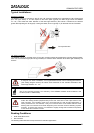
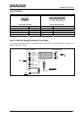
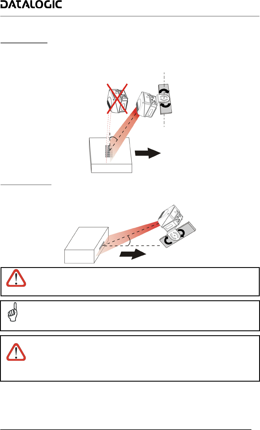
Standard Installation
The DS6500 scanner is mounted on the ST-237 106° mounting bracket which guarantees a built-in Skew angle
(S in the figure below) of 16° with respect to the frame plane (typically the Skew angle should be between
10° - 20°). This avoids the direct reflection of the laser light emitted by the scanner. Furthermore, the bracket
guides allow adjusting the Tilt angle (T in the figure below, which is typically 0°) for the best scanner orientation:
T
S
Conveyor Direction
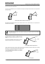
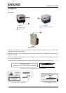
“45° Skew” Installation
The DS6500 scanner is mounted on the ST-210 90° mounting bracket. By adjusting the mounting bracket guides,
reach 45° for the Skew angle (S in the figure below) to avoid the direct reflection of the laser light emitted by the
scanner:
S
45°
ATTENTION
If using the “45° Skew” installation, it is not guaranteed that the scanner reading performances
(see reading diagram section) will match those measured for the standard installation with
Skew angle between 10° - 20°.
NOTE
The ST-210 mounting bracket is an accessory of the DS6500 standard model available in the
US-60 kit (order no. 890001020).
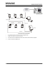
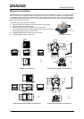
WARNING
When installing several scanners, take care to position them correctly so that no laser beam
enters the reading window perpendicularly and at the same level of the output beam of the
other scanners. This condition could occur more frequently for side mounted applications. If
these precautions are not followed, it may occur that the laser of the blinded scanner starts
blinking due to an internal circuit which temporarily turns the laser off when detecting a power
anomaly. To resolve this problem, it is sufficient to slightly change the inclination and position
of one of the two scanners involved.
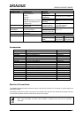
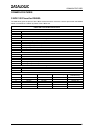
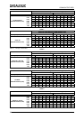
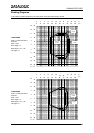
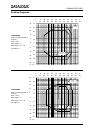
Reading Conditions:
• ANSI Grade B minimum
• 800 scans/sec
The following tables describe the requirements for standard applications.
27