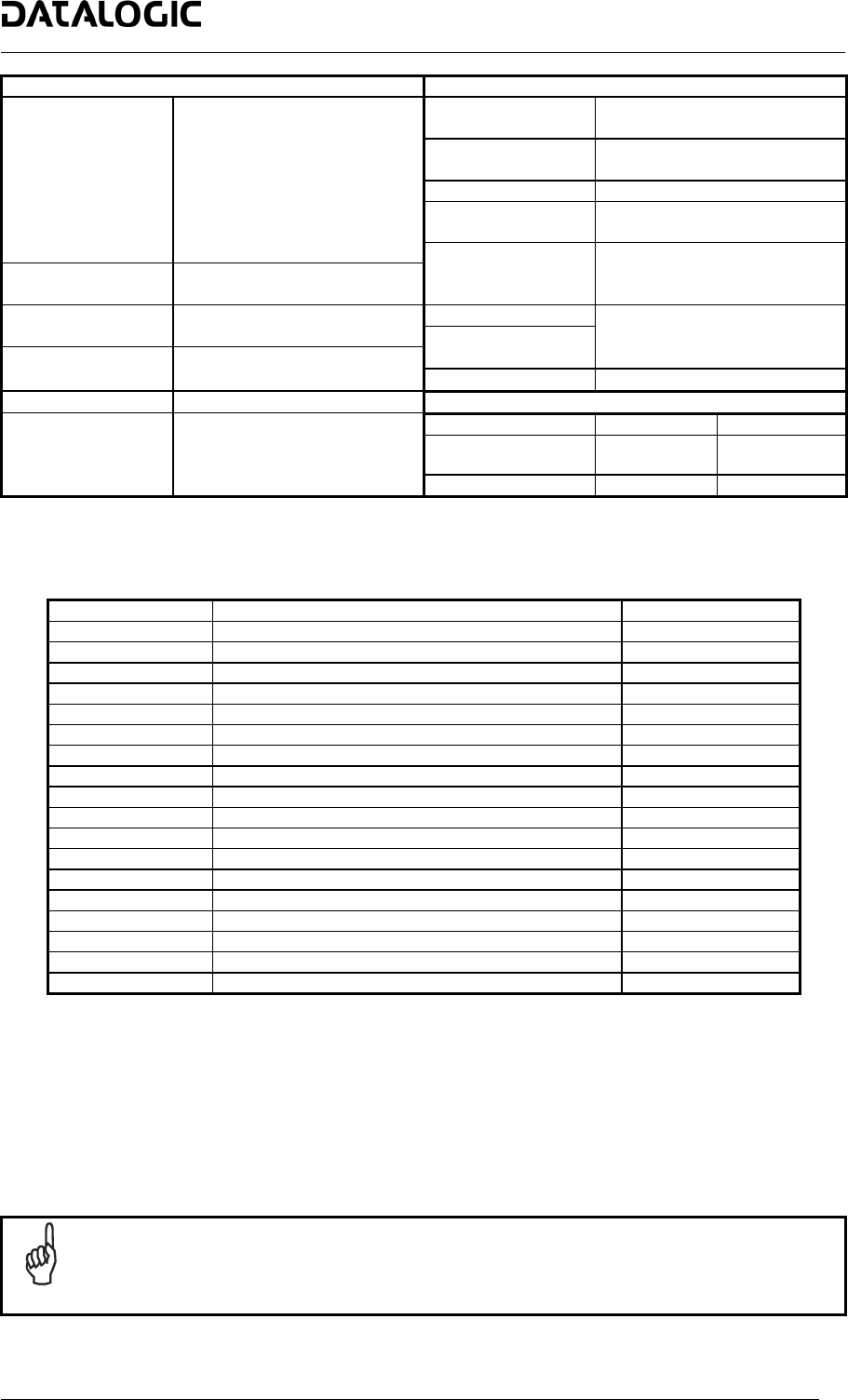
DS6500 DEVICENET MODEL
SOFTWARE FEATURES ENVIRONMENTAL FEATURES
Interleaved 2/5
Readable Codes
Code 39 standard
Operating
Temperature
0° to +40 °C (+32 to +104 °F)
Codabar
Code 128
Storage
Temperature
-20° to +70 °C (-4° to +158 °F)
EAN 128
Humidity
90% non condensing
Code 93 (Standard & Full ASCII)
Ambient Light
EAN/UPC (including Add-on 2
Immunity
3500 lux
And Add-on 5)
Vibration Resistance
14 mm @ 2 to 10 Hz
Code Selection
IEC 68-2-6 test FC 1.5 mm @ 13 to 55 Hz
Up to 10 codes during one
reading phase
2 hours on each axis 2 g @ 70 to 200 Hz
Headers and Shock Resistance
Terminators
Up to 128-byte headers and
128-byte terminators
IEC 68-2-27 test EA
On Line, Automatic, Test, 3 shocks on each axis
30 g; 11 ms
Operating Modes
PackTrack™
Protection Class
IP64
Config. Mode
Genius™ utility program
PHYSICAL FEATURES
Std Models Oscill. Mirror
Dimensions mm
(inch)
110x113x99
(4.33x4.45x3.9)
113x180x104.5
(4.45x7.08x4.11)
Parameter Storage
Non-volatile internal FLASH
Weight
1.5 kg (3.3 lb) 2.0 kg (4.4 lb)
Accessories:
Name Description Part Number
CAB-6011 Cable to C-BOX100 1 m 93A051221
CAB-6012 Cable to C-BOX100 2 m 93A051222
CAB-6015 Cable to C-BOX100 5 m 93A051223
C-BOX 100 Passive connection box 93ACC1510
INT-30 20 mA C.L. interface board for C-BOX 100 93A151022
GFC-60 90° mirror 93A201100
GFC-600 90° mirror close distance 93A201102
PWR-120 Power unit 110/230 V AC - 24 V DC 93ACC1530
BTK-6000 Terminator kit (5 pcs) 93ACC1710
PG6002 Single unit power supply – US 93ACC1718
PG6001 Single unit power supply – UK 93ACC1719
PG6000 Single unit power supply – EU 93ACC1720
FBK-6000 Fast bracket kit (2 pcs) 93ACC1721
US-60 Mounting bracket kit (5 pcs) for multisided stations 890001020
MEP-542 Photocell kit – PNP 93ACC1727
MEP-543 Photocell kit – NPN 93ACC1728
OEK-2 Optical encoder (10 m cable + spring) 93ACC1770
OEK-1 Optical encoder kit + 10 m cable 93ACC1600
Electrical Connections:
The DS6500 DeviceNet reader provides a 26-pin male D-sub connector for connection to power supply and
input/output signals.
A DeviceNet connector is used for connection to the remote Host, while a local Lonworks 9-pin female connector
connects the DeviceNet master to the first slave reader of the system.
NOTE
When using DeviceNet, the Main serial interface is disabled and must not be physically
connected.
19


