


DS6500 DEVICENET MODEL
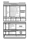
The details of the connector pins are indicated in the following table:
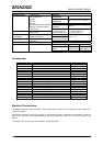
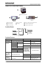
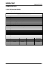
26-pin D-Sub Connector Pinout
Pin Name Function
Chassis - internally connected to GND
1 CHASSIS
Cable shield connected to chassis
20 RXAUX Receive data of auxiliary RS232 (referred to GND)
21 TXAUX Transmit data of auxiliary RS232 (referred to GND)
8 OUT 1+ Configurable digital output 1 – positive pin
22 OUT 1- Configurable digital output 1 – negative pin
11 OUT 2+ Configurable digital output 2 – positive pin
12 OUT 2- Configurable digital output 2 – negative pin
16 OUT 3A Configurable digital output 3 – polarity insensitive
17 OUT 3B Configurable digital output 3 – polarity insensitive
18 EXT_TRIG/PS A External trigger (polarity insensitive) for PS
19 EXT_TRIG/PS B External trigger (polarity insensitive) for PS
6 IN2/ENC A Input signal 2 (polarity insensitive) for Encoder
10 IN2/ENC B Input signal 2 (polarity insensitive) for Encoder
14 IN3A Input signal 3 (polarity insensitive)
15 IN4A Input signal 4 (polarity insensitive)
24 IN_REF Common reference of IN3 and IN4 (polarity insensitive)
9, 13 VS Supply voltage – positive pin
23, 25, 26 GND Supply voltage – negative pin
10
19
1
18
9
26
26-pin male D-sub Connector
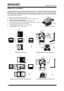
Pin RS232 RS485 Full-Duplex RS485 Half-Duplex
20 mA C.L
(INT-30 with C-BOX 100 only)
2 TX TX485+ RTX485+
3 RX RX485+
4 RTS TX485- RTX485- see INT-30 instructions
5 CTS RX485-
7 GND_ISO GND_ISO GND_ISO
* For 20 mA C.L. connections, GND is the same of the scanner power supply.
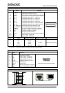
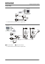
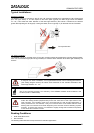
9-pin Lonworks Connector Pinout
Pin Name Function
Cable shield internally connected
1 CHASSIS
by capacitor to chassis
9 VS Supply voltage – positive pin
2 GND Supply voltage – negative pin
6 VS_I/O Supply voltage of I/O circuit
3 Ref_I/O Reference voltage of I/O circuit
4 SYS_ENC_I/O System signal
5 SYS_I/O System signal
7 LON A Lonworks line (polarity insensitive)
8 LON B Lonworks line (polarity insensitive)
5
1
9
6
9-pin female Local Lonworks Connector
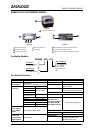
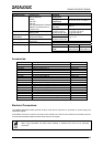
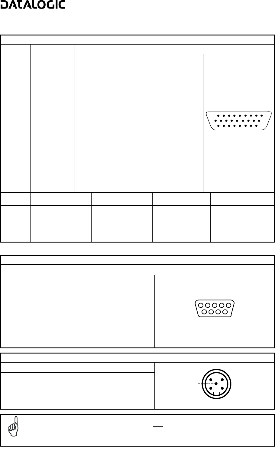
5-pin DeviceNet Connector Pinout
Pin Name Function
2 V+ Supply voltage – positive pin
5 CAN_L CAN bus data line – L
1 SHIELD Shield
4 CAN_H CAN bus data line – H
3 V- Supply voltage – negative pin
1
3
2
4
5
5
-
p
in m
a
l
e
D
e
vi
ce
N
et
Co
nn
ecto
r
NOTE
The power supplied on pin V+ and V- is used only to propagate power to the section of the
DeviceNet board directly connected to the Bus. It is completely isolated from the DS6500 power
which must be supplied on pin 9, 13 and pin 23, 25 of the 26-pin Main/Aux connector.
20