


Microprocessor Module: Dell Latitude 100L Service Manual
file:///C|/Work%20Area%20-%20A/E%20DOC%20Posting/latc100l/en/Service%20Manual/cpu.htm[2/4/2013 3:01:06 PM]
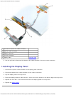
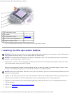
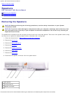
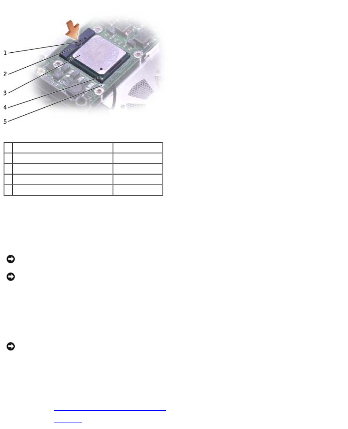
1 ZIF-socket cam screw
2 ZIF socket
3 microprocessor module see Mini RSL
4 pin-1 corner of microprocessor
5 triangle on system board
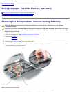
6. Use a microprocessor extraction tool to remove the microprocessor module.
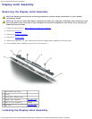
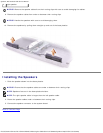
Installing the Microprocessor Module
NOTICE: Ensure that the cam lock is in the fully open position before seating the microprocessor module. Seating the
microprocessor module properly in the ZIF socket does not require force.
NOTICE: A microprocessor module that is not properly seated can result in an intermittent connection or permanent
damage to the microprocessor and ZIF socket.
1. Align the pin-1 corner of the microprocessor module so that it points to the triangle on the system board, and insert
the microprocessor module into the ZIF socket.
When the microprocessor module is correctly seated, all four corners are aligned at the same height. If one or more
corners of the module are higher than the others, the module is not seated correctly.
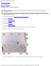
NOTICE: Hold the microprocessor down while turning the cam screw to prevent intermittent contact between the cam
screw and microprocessor.
2. Tighten the ZIF socket by turning the cam screw clockwise to secure the microprocessor module to the system board.
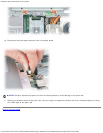
3. Wipe the thermal grease off of the microprocessor thermal-cooling assembly with a clean paper towel.
4. Squeeze all of the contents of the thermal grease packet (provided with the kit) on to the microprocessor thermal-
cooling assembly.
5. Replace the microprocessor thermal-cooling assembly.
6. Replace the EMI shield
.