


Back to Contents Page
Processor
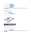
Removing the Processor
Replacing the Processor
Removing the Processor
1. Follow the instructions in Before You Begin.
2. Remove the system board (see Removing the System Board).
3. Remove the processor heat sink assembly (see Removing the Processor Heat Sink Assembly).
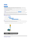
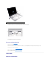
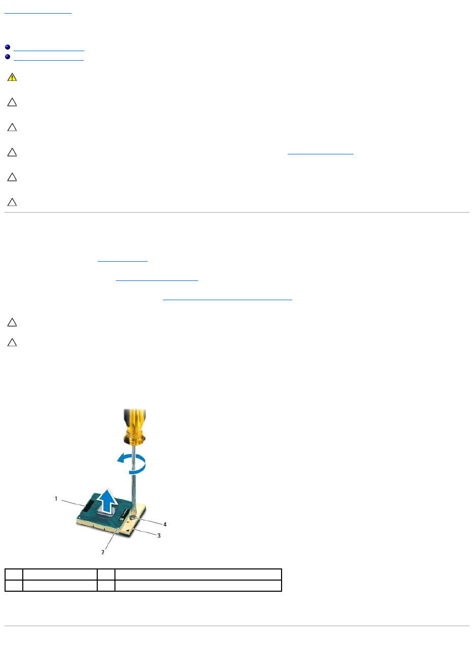
4. To loosen the ZIF socket, use a small, flat-blade screwdriver and rotate the ZIF-socket cam screw counterclockwise until it comes to the cam stop.
The ZIF-socket cam screw secures the processor to the system board. Take note of the arrow on the ZIF-socket cam screw.
5. Use a processor extraction tool to remove the processor.
Replacing the Processor
WARNING: Before working inside your computer, read the safety information that shipped with your computer. For additional safety best
practices information, see the Regulatory Compliance Homepage at www.dell.com/regulatory_compliance.
CAUTION: To avoid electrostatic discharge, ground yourself by using a wrist grounding strap or by periodically touching an unpainted metal
surface (such as a connector on your computer).
CAUTION: Onlyacertifiedservicetechnicianshouldperformrepairsonyourcomputer.DamageduetoservicingthatisnotauthorizedbyDell™
is not covered by your warranty.
CAUTION: To help prevent damage to the system board, remove the main battery (see Removing the Battery) before working inside the
computer.
CAUTION: To prevent intermittent contact between the ZIF-socket cam screw and the processor when removing or replacing the processor, press
to apply slight pressure to the center of the processor while turning the cam screw.
CAUTION: To avoid damage to the processor, hold the screwdriver such that it is perpendicular to the processor when turning the cam screw.
CAUTION: When removing the processor, pull it straight up. Be careful not to bend the pins on the processor.
CAUTION: To prevent intermittent contact between the ZIF-socket cam screw and the processor when removing or replacing the processor, press
to apply slight pressure to the center of the processor while turning the cam screw.
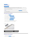
1
processor
2
pin-1 corner of processor
3
ZIF socket
4
ZIF-socket cam screw