


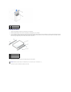

Most interface connectors are keyed for correct insertion; that is, a notch or a missing pin on one connector matches a tab or a filled-in hole on the other
connector. Keyed connectors ensure that the pin-1 wire in the cable (indicated by the colored stripe along one edge of the cable) goes to the pin-1 end of the
connector. The pin-1 end of a connector on a board or a card is usually indicated by a silk-screened "1" printed directly on the board or card.
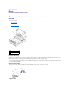
Removing a Hard Drive
1. If you are replacing a hard drive that contains data you want to keep, back up your files before you begin this procedure.
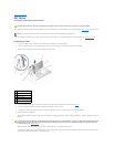
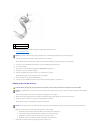
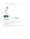
2. Disconnect the power and hard-drive cables from the drive.
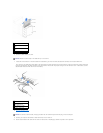
3. Press in on the tabs on each side of the drive and slide the drive up and out.
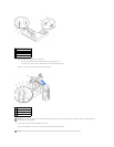
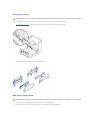
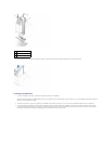
1
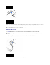
power cable
2
power input connector
1
interface connector
2
colored stripe on edge of
interface cable
3
interface cable
NOTICE: When you connect an interface cable, do not place the colored stripe away from pin 1 of the connector. Reversing the cable prevents the drive
from operating and could damage the controller, the drive, or both.
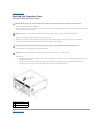
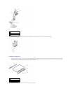
CAUTION: Before you begin any of the procedures in this section, follow the safety instructions in the System Information Guide.
NOTICE: To avoid damage to the drive, do not set it on a hard surface. Instead, set the drive on a surface, such as a foam pad, that will sufficiently
cushion it.
1
power cable
2
hard-drive cable