


7-4 Dell PowerEdge 4100/180 and 4100/200 Systems Installation and Troubleshooting Guide
R
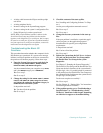
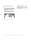
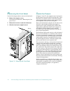
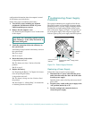
emoving the Front Bezel
Use the following procedure to remove the front bezel:
1. Remove the computer covers.
See the previous subsection, “Removing the Com-
puter Covers.”
2. Release the two tabs on each side of the bezel.
3. Slide the front bezel straight forward.
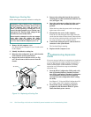
Figure 7-3. Removing the Front Bezel
I
nside the Chassis
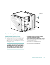
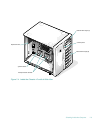
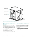
In Figures 7-4 and 7-5, the computer cover is removed to
provide interior views from the left and right sides. These
illustrations also identify features on the front and back
of the computer. Refer to them to locate interior features
and components discussed later in this guide.
When you look inside the computer, note the direct current
(DC) power cables leading from the power supply or
optional power-supply paralleling board. These cables
supply power to the system board, small computer sys-
tem interface (SCSI) backplane board, externally
accessible drives, and certain expansion cards that con-
nect to external peripherals.
The flat ribbon cables are the interface cables for internal
drives. For non-SCSI drives, an interface cable connects
each drive to an interface connector on the system board
or on an expansion card. For SCSI devices, two interface
cables connect externally accessible SCSI devices and
the SCSI backplane board to a SCSI host adapter either
on the system board or on an expansion card.
The system board—the large, vertical printed circuit board
at the left side of the chassis near the back—holds the
computer’s control circuitry and other electronic compo-
nents. Some hardware options are installed directly onto
the system board. The system board provides eight expan-
sion-card connectors. The external drive bays provide space
for up to four half-height drives, typically diskette drives,
CD-ROM drives, or tape drives. The internal drive bays
provide space for up to six half-height SCSI hard-disk
drives. These drives are connected to the SCSI host
adapter via the SCSI backplane board, which manages the
drive bays and monitors the drive environment, including
voltages and temperatures.
During an installation or troubleshooting procedure, you
may be required to change a jumper or switch setting on the
system board, an expansion card, or a drive. For informa-
tion on the system board jumpers, see Appendix C,
“Jumpers and Switches.”
tabs (4)