


Installing Drives in the External Bays 9-3
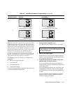
Removing and Replacing Front-Panel
Inserts
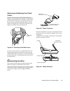
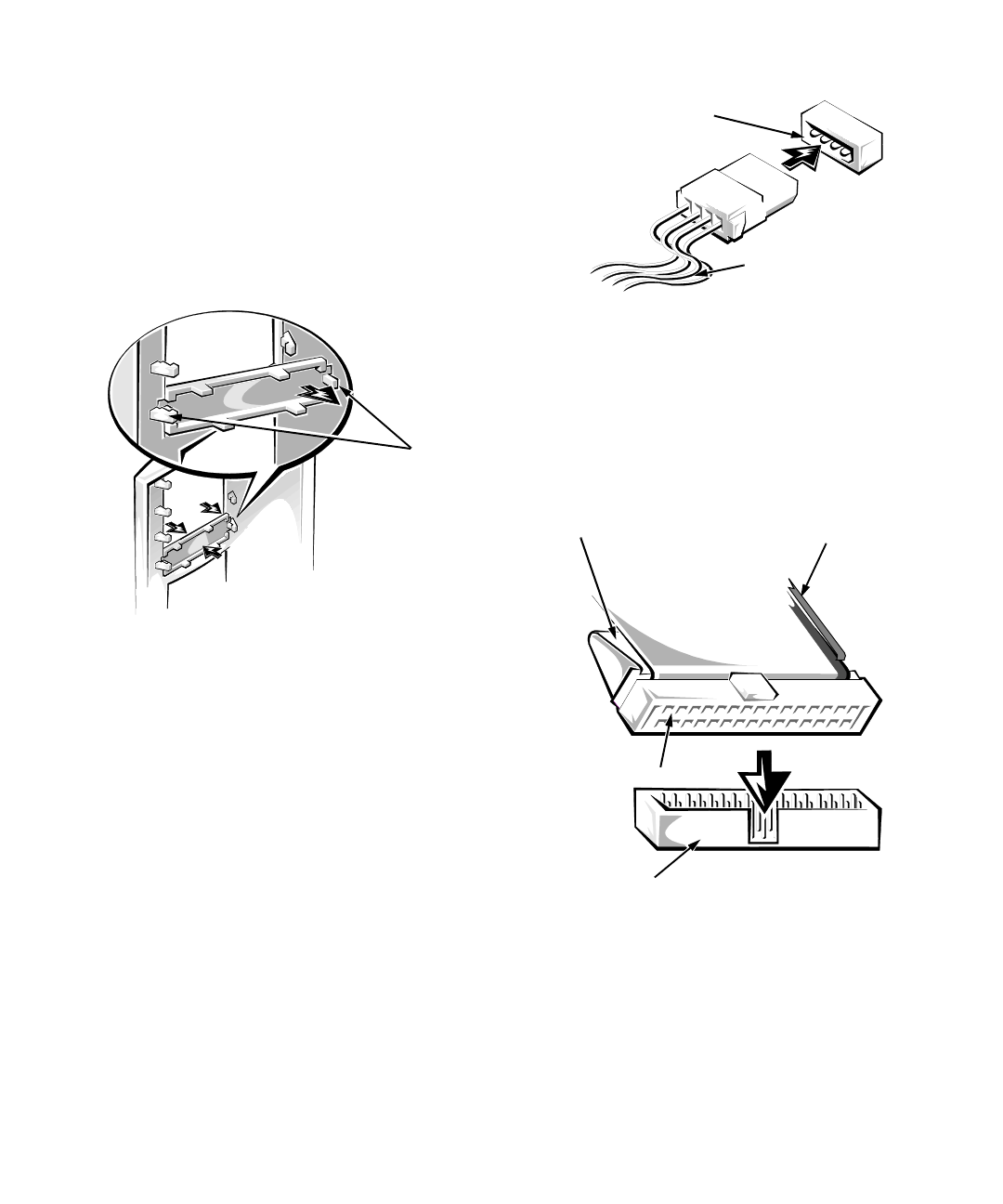
To remove the front-panel insert for a drive bay you
intend to use, first remove the front bezel as instructed in
“Removing the Front Bezel” in Chapter 7. Then, facing
the inside of the front bezel, press against the center of
the insert with your thumbs until the insert bows suffi-
ciently to loosen the tabs on the sides of the insert (see
Figure 9-2). Pull the insert out of the bezel.
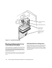
Figure 9-2. Removing a Front-Panel Insert
To replace a front-panel insert, position the insert over
the bay opening from the inside of the front bezel and
carefully press the insert into place. A tab on each side of
the insert snaps into a corresponding latch on the inside
of the front bezel.
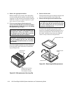
C
onnecting the Drive
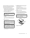
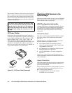
This section describes the power input connectors and
interface connectors on the backs of most drives.
Figure 9-3 shows the 4-pin power input connector, where
you connect a direct current (DC) power cable from the
system power supply or power-supply paralleling
board.
Figure 9-3. Power Connectors
The power connectors are keyed to avoid incorrect inser-
tion; do not force two connectors together if they do not
fit properly.
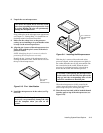
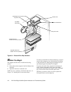
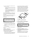
A ribbon cable (see Figure 9-4) functions as the interface
cable for most types of drives.
Figure 9-4. Header Connector
tabs
power input
connector on the drive
DC power cable (from
the power supply)
header connector
interface connector
pull tab
colored strip
on ribbon cable