


System Board: Dell Latitude C610/C510 Service Manual
file:///C|/Work%20Area%20-%20A/E%20DOC%20Posting/latc610/service%20manual/sysboard.htm[2/1/2013 11:00:52 AM]
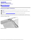
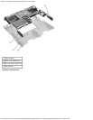
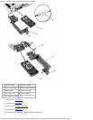
11. Remove the speakers from the bottom case.
12. Pull the right side of the bottom case, next to the external headphone and microphone connectors, away from the
system board as you simultaneously lift the front of the system board out and away from the bottom case.
Replacing the System Board
1. Install the microprocessor on the replacement system board.
2. Connect the right and left speakers
to the replacement system board.
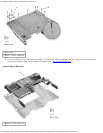
3. Install the replacement system board.
a. Insert the external microphone and headphone connectors through the bottom case.
b. Replace the six M2.5 x 5-mm screws, starting on the right side of the bottom case (see "System Board Screw
Removal").
c. Replace the fan guard, inserting the tab into the bottom case, and replace the three M2.5 x 5-mm screws (see
"System Board Screw Removal"). Replacing the screw opposite the tab first makes it easier to insert and replace
the other two screws.
4. Replace the modem, the speaker assemblies, and the microprocessor thermal cooling assembly that you removed from
the old system board.
NOTE: Be sure to route cables so that they will not be crimped or pinched when the complete assembly is put
back together.
5. Replace the palm rest, the keyboard, the display assembly, and the hard drive.
6. Replace the module bay devices and any PC Cards or plastic blanks in the PC Card slot.
7. Insert the floppy disk or CD that accompanied the replacement system board into the appropriate drive, and turn on
the computer. Follow the instructions on the screen.
NOTE: After replacing the system board, be sure to enter the computer service tag sequence into the BIOS of
the replacement system board.
Back to Contents Page