


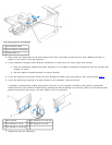
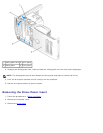
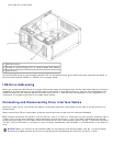

Up to two CD or DVD drives
1 CD/DVD drive(s)
2 FlexBay for optional floppy drive or optional Media Card Reader
3 hard drive(s)
Connect CD/DVD drives to the connector labeled "IDE" on the system board. Serial ATA hard drives should be connected to
the connectors labeled "SATA0" or "SATA2" on the system board.
IDE Drive Addressing
When you connect two IDE devices to a single IDE interface cable and configure them for the cable select setting, the device
attached to the last connector on the interface cable is the master or boot device (drive 0), and the device attached to the
middle connector on the interface cable is the slave device (drive 1). See the drive documentation in your upgrade kit for
information on configuring devices for the cable select setting.
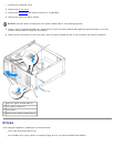
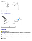
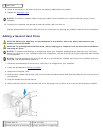
Connecting and Disconnecting Drive Interface Cables
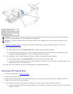
When you install a drive, you connect two cables—a DC power cable and a data cable—to the back of the drive and to the
system board.
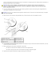
When removing an IDE drive data cable, grasp the colored pull-tab and pull until the connector detaches.
Most interface connectors are keyed for correct insertion; that is, a notch or a missing pin on one connector matches a tab or
a filled-in hole on the other connector. Keyed connectors ensure that the pin-1 wire in the cable (indicated by the colored
stripe along one edge of the IDE cable—serial ATA cables do not use a colored stripe) goes to the pin-1 end of the connector.
The pin-1 end of a connector on a board or a card is usually indicated by a silk-screened "1" printed directly on the board or
card.
NOTICE: When you connect an IDE interface cable, do not place the colored stripe away from pin 1 of the connector.
Reversing the cable prevents the drive from operating and could damage the controller, the drive, or both.