


DELL E173FP Service Manual
30
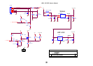
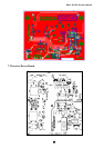
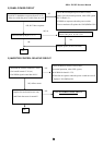
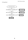
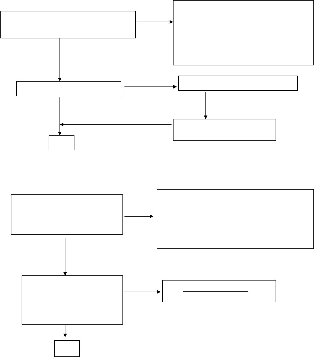
2) PANEL-POWER CIRCUIT
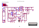
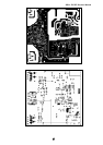
3) INVERTER CONTROL RELATIVE CIRCUIT
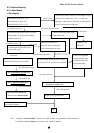
Check R172 should have response from 0V to 5V
When we switch the power switch from on to off
NG
Check the PPWR panel power relative circuit,
Q105, Q104 In normal operation, when LED =green,
R172 should =5 v,
If PPWR no-response when the power switch
Turn on and turn off, replace the U102(GMZan3-SL)
OK
,
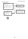
R172 have res
p
onse
NG, no
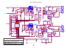
Measured the Q104 pin 3= 5 V?
Check U202 pin 4, 16, 28=3.3V?
OK
OK
Replace Q104 ( N-mos, AO3401)
Yes
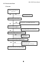
Measured the inverter connector CN104
Pin1 on/off control=3.3V (on)
Pin2 PWM signal control dim 0V-5V
NG
Check the Bklt-On relative circuit, R162,
In normal operation, when LED =green,
R162 Bklt-On should =3.3V,
If Bklt-On no-response when the power switch turn on-off,
Replace U102 GMZan3-SL
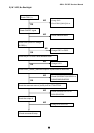
NG, still no screen
Replace Inverter board to new-one,
and Check the screen is normal??
OK
NG
Check NO SCREEN APPEAR block