


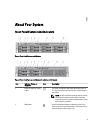
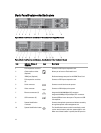
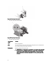
Back-Panel Features And Indicators
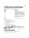
Figure 5. Back-Panel Features and Indicators—Redundant Power Supply Unit Chassis
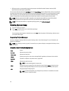
Figure 6. Back-Panel Features and Indicators—Non-Redundant Power Supply Unit Chassis
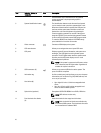
Item Indicator, Button, or
Connector
Icon Description
1 PCIe expansion card slot 1 Connects a PCI Express expansion card.
2 vFlash media card slot
(Optional)
Allows you to insert a vFlash media card.
3 iDRAC port (Optional) Dedicated management port for the iDRAC Ports Card.
4 PCIe expansion card slots
(3)
Connects a PCI Express expansion card.
5 Serial connector Connects a serial device to the system.
6 Video connector Connects a VGA display to the system.
7 Ethernet connectors (2)
Integrated 10/100/1000 Mbps NIC connector
Integrated 100 Mbps/1 Gbps/10 Gbps SFP+ connector
8 USB connectors (2) Connect USB devices to the system. The ports are USB
2.0-compliant.
9 System identification
connector
Connects the optional system status indicator assembly
through the optional cable management arm.
10 System identification button The identification buttons on the front and back panels
can be used to locate a particular system within a rack.
When one of these buttons is pushed, the LCD panel on
14