


Assembling The DC Input Power Wires
WARNING: For equipment using –(48–60) V DC power supplies, a qualified electrician must perform all
connections to DC power and to safety grounds. Do not attempt connecting to DC power or installing grounds
yourself. All electrical wiring must comply with applicable local or national codes and practices. Damage due to
servicing that is not authorized by Dell is not covered by your warranty. Read and follow all safety instructions that
came with the product.
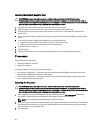
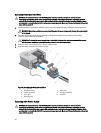
1. Strip the insulation from the ends of the DC power wires, exposing approximately 13 mm (0.5 inch) of copper wire.
WARNING: Reversing polarity when connecting DC power wires can permanently damage the power supply
or the system.
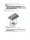
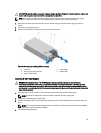
2. Insert the copper ends into the mating connectors and tighten the captive screws at the top of the mating
connector using a #2 Phillips screwdriver.
WARNING: To protect the power supply from electrostatic discharge, the captive screws must be covered
with the rubber cap before inserting the mating connector into the power supply.
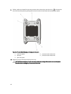
3. Rotate the rubber cap clockwise to fix it over the captive screws.
4. Insert the mating connector into the power supply.
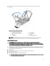
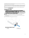
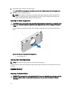
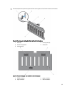
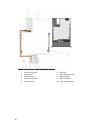
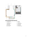
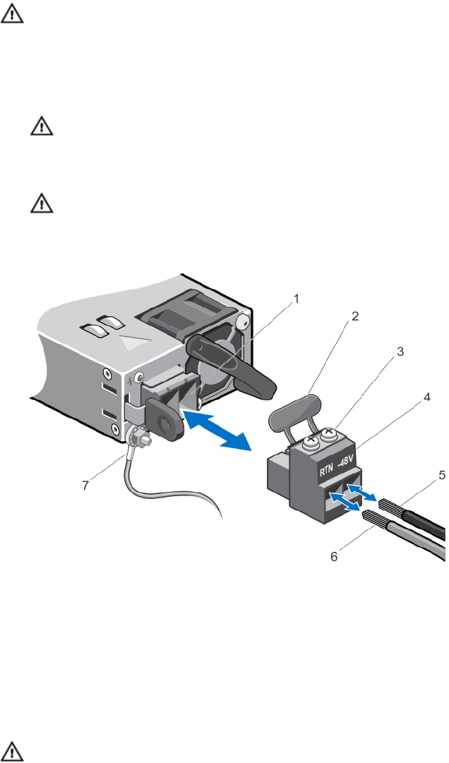
Figure 52. Assembling the DC Input Power Wires
1. DC power socket 2. rubber cap
3. captive screws (2) 4. DC power connector
5. wire –48 V 6. wire RTN
7. grounding wire
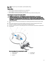
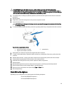
Removing A DC Power Supply
WARNING: For equipment using –(48–60) V DC power supplies, a qualified electrician must perform all
connections to DC power and to safety grounds. Do not attempt connecting to DC power or installing grounds
yourself. All electrical wiring must comply with applicable local or national codes and practices. Damage due to
servicing that is not authorized by Dell is not covered by your warranty. Read and follow all safety instructions that
came with the product.
92