


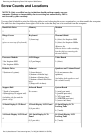

Screw Counts and Locations
NOTICE: Only a certified service technician should perform repairs on your
computer. Damage or inoperability due to servicing not authorized by Dell is
not covered by your warranty.
You may find it helpful to print the following table to use for keeping the screws organized as you disassemble the computer.
The table lists the components from right to left in the order that they are to be removed from the computer.
Hard-Disk Drive
1
Memory
2
Modem
2
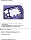
Hinge Covers
2
(piece across top of keyboard)
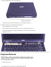
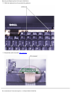
Keyboard
2 (from top)
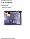
Thermal Shield
4 (silver) for Inspiron 5000
5 (silver) for Inspiron 5000e
(Remove the
diskette-drive-cable retaining
bracket before removing the
thermal shield.)
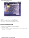
Processor Module
3 for Inspiron 5000
2 for Inspiron 5000e
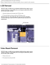
LCD Hinges
4 (2 per hinge)
Video Board
1 (silver)
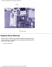
Diskette Drive
2 (bottom of system)
Palmrest
3 (from the top)
4 (bottom of media bay)
5 (bottom of battery bay)
3 (bottom of hard-disk drive
bay)
5 (deep wells in base)
Speakers and Volume Board
9 (do not unscrew the
speakers)
(including both speakers and
the volume board)
Support Rail
7 (back of computer)
4 (through top of support rail)
(including the fan and the
plastic strip)
Infrared Board
No screws
System Board
2 (serial port nuts)
2 (parallel port nuts)
2 (VGA port nuts)
2 (APR/PPR port nuts)
2 (screws into base)
15-Inch Display LCD Bezel
2
15-Inch Display LCD Panel
8 (4 per side)
15-Inch Display LCD
Locking Tabs
4 (2 each)
14.1-Inch Display LCD Bezel
4
14.1-Inch Display LCD
Panel
6 (3 per side)
14.1-Inch Display LCD
Locking Tabs
4 (2 each)
Removing and Replacing Parts: Dell Inspiron 5000 Series
file:///c|/docs/blanco E-doc/removing.htm (7 of 29) [9/1/2000 3:31:59 PM]