


CMC Module
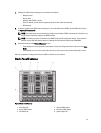
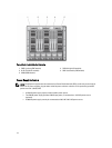
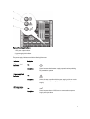
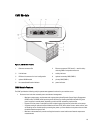
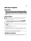
Figure 12. CMC Module Features
1 Ethernet connector Gb1 2 Ethernet connector STK ("stack") - used for daisy-
chaining CMCs in separate enclosures
3 link indicator 4 activity indicator
5 DB-9 serial connector for local configuration 6 optional secondary CMC (CMC 2)
7 optional iKVM module 8 primary CMC (CMC 1)
9 blue status/identification indicator 10 power indicator
CMC Module Features
The CMC provides the following multiple systems management functions for your modular server:
• Enclosure-level real-time automatic power and thermal management.
– Monitors system power requirements and supports the optional Dynamic Power Supply Engagement
(DPSE) mode. The DPSE mode improves power efficiency by allowing the CMC to dynamically place
power supplies in standby mode, depending on the load and redundancy requirements.
– Reports real-time power consumption, which includes logging high and low points with a time stamp.
– Supports setting an optional enclosure Maximum Power Limit, which either alerts or takes actions, such
as throttling server modules and/or preventing the power up of new blades to keep the enclosure under
the defined maximum power limit.
– Monitors and automatically controls cooling fans based on actual ambient and internal temperature
measurements.
19