


M3601Q 16+16 Port 40Gb/s InfiniBand Switch User Manual
Mellanox Technologies Rev 1.7
7
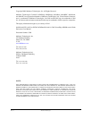
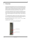
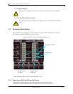
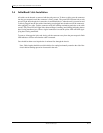
1.1 InfiniBand Connectors
InfiniBand connectivity has 8 microGiGa connectors through the front panel. The remaining 16
interfaces are through the AirMax Midplane Connector out the back of the switch.
Figure 1 shows
the front 8 ports.
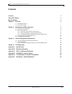
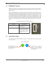
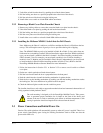
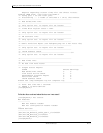
Each of the InfiniBand ports has two LEDs located next to the connector. The green LED, when lit,
indicates that a valid physical connection to the other system (switch or HCA port) exists. The yel
-
low LED when lit, indicates that the Subnet Manager is running and a valid data link exists. The
yellow LED illuminates when the InfiniBand network is discovered over the physical link. A valid
data activity link without data transfer is designated by a constant yellow LED indication. A valid
data activity link with data transfer is designated by a blinking yellow LED indication. If the LEDs
are not active, either the physical link or the logical link (or both) connections have not been estab
-
lished.
Figure 2: Physical and Logical Link Indication LEDs
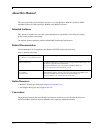
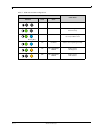
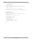
1.2 Switch Status Lights
The switch Status lights indicate whether the switch is receiving power from the chassis, and the
state of the switch.
Figure 3: Indicator LEDs
LED Name Connection Status
Physical Link - Green Off – No Physical Link
ON – Physical Link
Data Activity - Yellow Blinking – indicates Data Transfer
Constant on – indicates Link exists
with no Data Transfer taking place
Off with green LED lit – indicates that
the Subnet Manager may not be
running
The I/O Module is on and
ready when both the blue and
green LEDs are lit.
This LED can be blue or
amber. A fault is indicated
when the amber LED is blink-
ing. See Table 3.