


4 Dell M8428-k Hardware Reference Manual
53-1001980-01
Hardware description
1
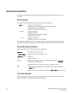
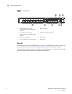
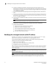
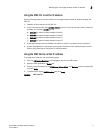
FIGURE 1 Port side view
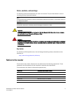
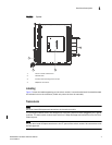
Top view
The nonport side of the switch module (shown in Figure 2) is seated into the enclosure. You do not
need to line up the switch module as it will seat correctly when the release lever is closed.
When the switch module is inserted, the midplane connectors activate a connection port, allowing
the switch module to be configured in the Blade Server Enclosure.
1 10 GbE CEE ports with bi-color
(green/amber) port status LEDs above
each port
2 RJ45 console port
3 8 Gbps FC ports with bi-color
(green/amber) port status LEDs above
each port
4Switch status LED (green/amber)
5 Power status LED (green) 6 Release latch
7 Server management LED (blue/amber) 8 Release lever
M8428 -k
21
7 68
45
3