


42 Display Assembly
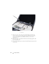
6
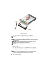
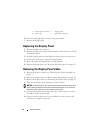
Disconnect the light lobes connector using the pull-tab.
7
Remove the display panel.
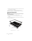
Replacing the Display Panel
1
Replace the light lobes connector.
2
Replace the eight screws that attach the display panel brackets to each side
of the display panel.
3
Align the display panel with the display back and replace the four screws.
4
Connect the LCD camera cable to the display panel.
5
Route the cables back through their routing channels.
6
Replace the display bezel (see "Replacing the Display Bezel" on page 41).
Removing the Display Panel Cable
1
Remove the display assembly (see "Removing the Display Assembly" on
page 37).
2
Remove the display bezel (see "Removing the Display Bezel" on page 40).
3
Remove the display panel (see "Removing the Display Panel" on page 41).
4
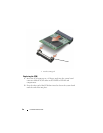
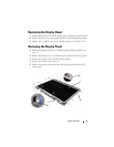
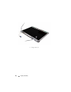
Turn over the display panel, placing it on a clean surface.
NOTICE: To avoid damage to the computer when replacing the bottom flex cable,
gently support the bottom of the inverter board with one finger as you reseat the
bottom flex-cable connector. Do not bend the inverter board.
5
Gently pull the pull-tab from the bottom flex-cable connector to release
the cable from the inverter board.
6
Squeeze the flex-cable release levers at either side of the top flex-cable
connector, releasing the connector.
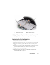
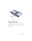
1 camera cable connector 2 display panel
3 screws (12) 4 light lobes connector