


Powerful Solutions for Digital Plants
MYNAH Technologies 504 Trade Center Blvd. Chesterfield, MO 63005 Telephone 636 681-1555 Fax 636 681-1660
www.mynah.com
25
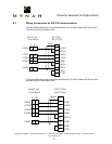
There are additional switches on the 1785-KE Module (Series B) which may require
adjustment. Refer to the Allen-Bradley User Manual for further information.
· SW1 - RS232C link features
· SW2 - Node number
· SW3 - Data highway Plus and RS-232C communication baud rates, and
Local/Remote option
· SW4 - Reserved for future use.
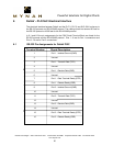
A.3 1770-KF2 Module Switch Settings
The 1770-KF2 module has 6 switch assemblies which allow the selection of various
communications options. The 1770-KF2 Module RS-232C parameters should be set up
as follows:
· Full duplex
· Same parity as configured for the DeltaV PSIC Port
· BCC error checking
· RS-232 communications baud rate same as DeltaV PSIC Port
· Hardware handshake on
· Duplicate messages - ignore
· Execute diagnostic commands
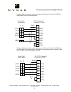
There are additional switches on the 1770-KF2 module which may require adjustment.
Refer to the Allen-Bradley User Manual for further information.
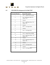
· SW1 – Configure with parameters as defined above
· SW2/SW3/SW4 – Unique Station number for DH+
· SW5 - Data highway communication baud rate at 57.6k
· SW6 – Computer link baud rate and diagnostic commands
· SW7 – Data Highway +
· SW8 – RS-232
NOTES: Dip switch changes do not take affect until power is cycled on the KF2.
The fourth switch on SW1 must be set to ON. This enables hardware handshaking.