


DS_DNM04SMD10_07162008
6
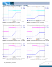
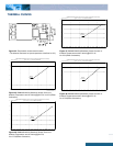
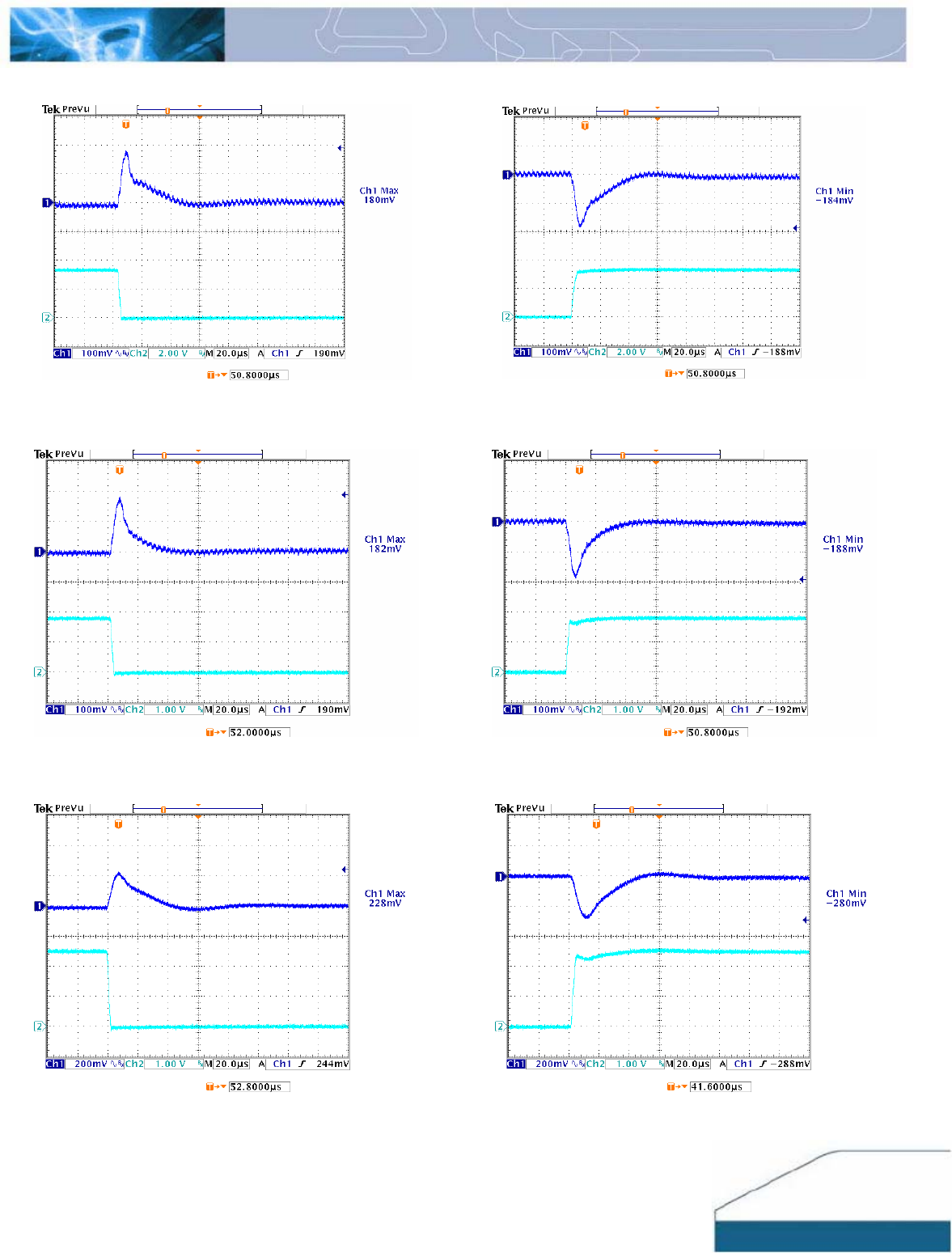
ELECTRICAL CHARACTERISTICS CURVES
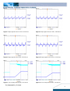
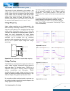
Figure 19: Typical Transient Response to Step Load Change at
2.5A/μS from 100% to 50% of Io, max at 5Vin, 3.3Vout
(Cout = 1uF ceramic, 10μF Tantalum)
Figure 20: Typical Transient Response to Step Load Change at
2.5A/μS from 50% to 100% of Io, max at 5Vin, 3.3Vout
(Cout =1uF ceramic, 10μF Tantalum)
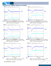
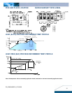
Figure 21: Typical Transient Response to Step Load Change at
2.5A/μS from 100% to 50% of Io, max at 5Vin, 1.8Vout
(Cout =1uF ceramic, 10μF Tantalum)
Figure 22: Typical Transient Response to Step Load Change at
2.5A/μS from 50% to 100% of Io, max at 5Vin, 1.8Vout
(Cout = 1uF ceramic, 10μF Tantalum)
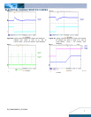
Figure 23: Typical Transient Response to Step Load Change at
2.5A/μS from 100% to 50% of Io, max at 3.3Vin,
2.5Vout (Cout =1uF ceramic, 10μF Tantalum)
Figure 24: Typical Transient Response to Step Load Change at
2.5A/μS from 50% to 100% of Io, max at 3.3Vin,
2.5Vout (Cout =1uF ceramic, 10μF Tantalum)