


DS_DNM04SMD10_07162008
11
FEATURE DESCRIPTIONS (CON.)
The amount of power delivered by the module is the
voltage at the output terminals multiplied by the output
current. When using the trim feature, the output voltage
of the module can be increased, which at the same
output current would increase the power output of the
module. Care should be taken to ensure that the
maximum output power of the module must not exceed
the maximum rated power (
Vo.set x Io.max ≤ P max).
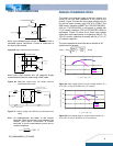
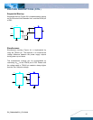
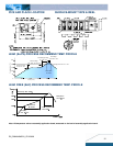
Voltage Margining
Output voltage margining can be implemented in the
DNL modules by connecting a resistor, R margin-up, from the
Trim pin to the ground pin for margining-up the output
voltage and by connecting a resistor, R
margin-down, from the
Trim pin to the output pin for margining-down. Figure 39
shows the circuit configuration for output voltage
margining. If unused, leave the trim pin unconnected.
A
calculation tool is available from the evaluation
procedure which computes the values of R
margin-up and
R
margin-down for a specific output voltage and margin
percentage.
Vo
On/Off
Vin
GND
Trim
Q2
Q1
Rmargin-up
Rmargin-down
Rtrim
Figure 39: Circuit configuration for output voltage margining
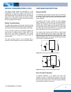
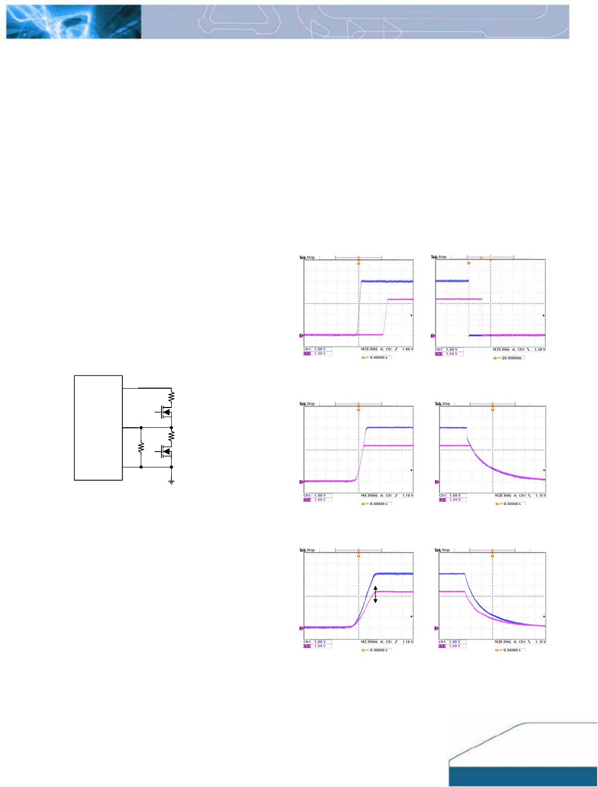
Voltage Tracking
The DNM family was designed for applications that have
output voltage tracking requirements during power-up
and power-down. The devices have a TRACK pin to
implement three types of tracking method: sequential
start-up, simultaneous and ratio-metric. TRACK
simplifies the task of supply voltage tracking in a power
system by enabling modules to track each other, or any
external voltage, during power-up and power-down.
By connecting multiple modules together, customers can
get multiple modules to track their output voltages to the
voltage applied on the TRACK pin.
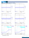
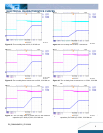
The output voltage tracking feature (Figure 40 to Figure
42) is achieved according to the different external
connections. If the tracking feature is not used, the
TRACK pin of the module can be left unconnected or tied
to Vin.
For proper voltage tracking, input voltage of the tracking
power module must be applied in advance, and the
remote on/off pin has to be in turn-on status. (Negative
logic: Tied to GND or unconnected. Positive logic: Tied to
Vin or unconnected)
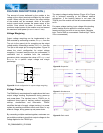
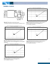
Figure 40: Sequential
Figure 41: Simultaneous
Figure 42: Ratio-metric
PS1
PS2
PS1
PS2
PS1
PS2
PS1
PS2
+△V
PS2
PS1
PS2
PS1