


DS_DNM04SMD10_07162008
9
DESIGN CONSIDERATIONS (CON.)
The power module should be connected to a low
ac-impedance input source. Highly inductive source
impedances can affect the stability of the module. An
input capacitance must be placed close to the modules
input pins to filter ripple current and ensure module
stability in the presence of inductive traces that supply
the input voltage to the module.
Safety Considerations
For safety-agency approval the power module must be
installed in compliance with the spacing and separation
requirements of the end-use safety agency standards.
For the converter output to be considered meeting the
requirements of safety extra-low voltage (SELV), the
input must meet SELV requirements. The power
module has extra-low voltage (ELV) outputs when all
inputs are ELV.
The input to these units is to be provided with a
maximum 15A time-delay fuse in the ungrounded lead.
FEATURES DESCRIPTIONS
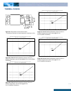
Remote On/Off
The DNM/DNL series power modules have an On/Off pin
for remote On/Off operation. Both positive and negative
On/Off logic options are available in the DNM/DNL series
power modules.
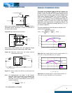
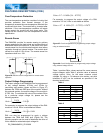
For positive logic module, connect an open collector
(NPN) transistor or open drain (N channel) MOSFET
between the On/Off pin and the GND pin (see figure 34).
Positive logic On/Off signal turns the module ON during
the logic high and turns the module OFF during the logic
low. When the positive On/Off function is not used, leave
the pin floating or tie to Vin (module will be On).
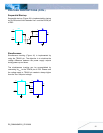
For negative logic module, the On/Off pin is pulled high
with an external pull-up 5kΩ resistor (see figure 35).
Negative logic On/Off signal turns the module OFF during
logic high and turns the module ON during logic low. If the
negative On/Off function is not used, leave the pin floating
or tie to GND. (module will be On)
RL
Vo
Vin
On/Off
GND
I
ON/OFF
Figure 34: Positive remote On/Off implementation
Vo
Vin
On/Off
GND
Rpull-up
RL
I
ON/OFF
Figure 35: Negative remote On/Off implementation
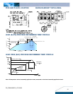
Over-Current Protection
To provide protection in an output over load fault
condition, the unit is equipped with internal over-current
protection. When the over-current protection is triggered,
the unit enters hiccup mode. The units operate normally
once the fault condition is removed.