


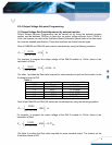
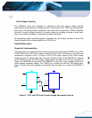
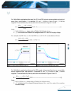
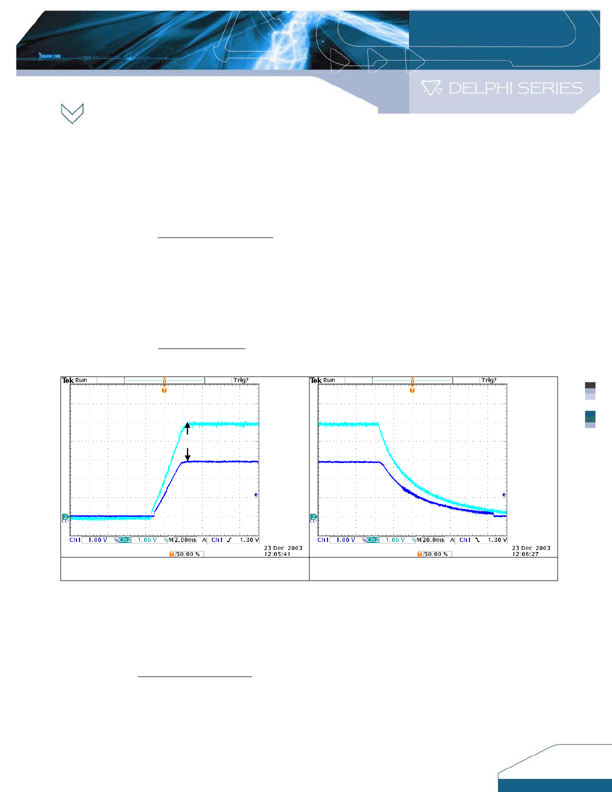
For Ratio-Metric applications that need the PS1 and PS2 outputs arrive regulation set point at
same time, use equation 1 to calculate R1, set △ V=Vo
set,PS1
–Vo
set,PS2
and △ V will be
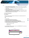
negative. The waveforms of power up and down are showed in Figures 7 and 8.
K
Vref
VrefVVo
R
PSset
20*
])[(
1
2,
−∆+
=
Ω
------------------------------------------------------(1)
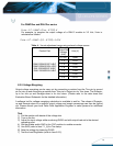
Note:
1. Vref =0.4×Vo
set,PS2
, please refer to Table 5 for Vref set value.
2. △V is the maximum difference of voltage between PS1 and PS2 supply voltage.
For example, the PS1 Vo
set,PS1
=5V, the PS2 Vo
set,PS2
=3.3V, R1 is calculated as follows:
KKR 75.5520*
32.1
]32.1)7.13.3[(
1 =
−+
=
Ω
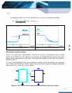
Figure 7. Ratio–metric tracking Power up Figure 8. Ratio–metric tracking Power down
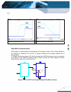
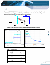
For Ratio-Metric applications that need the PS2 supply voltage rises first at power up and falls
second at power down, use equation 2 to calculate R1, set △V≦0.4×Vo
set,PS2
and △V will be
negative. The waveforms of power up and down are showed in Figures 9 and 10.
K
Vref
VrefVVo
R
psset
20*
])[(
1
2,
−∆−
=
-----------------------------------------------------------------(2)
Note:
1. Vref =0.4×Vo
set,PS2
, please refer to Table 5 for Vref set value.
2. △V is defined as the voltage difference between Vo
PS1
and Vo
PS2
when Vo
PS2
reaches
its rated voltage.
13
PS1=5
V
PS2=3.3V
PS1
PS2
+△V=1.7V