


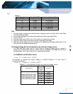
Table 2.
Vo,set
Rset (k
Ω
) R33
Recommend Value, R//R
0.7525 Open Open
1.2 22.464 23.7k//432k
1.5 13.047 14.0k//191k
1.8 9.024 9.53k//169k
2.5 5.009 5.23k//118k
3.3 3.122 3.16k//261k
5.0 1.472 1.5k//78.7k
Test
1. Put the resistor to program the desired output voltage set point by follow Table 1 and Table
2 for the standard output.
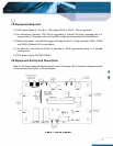
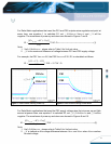
2. Set the input voltage to the desired operating level while monitoring DVM2.
3. Turn on the fan.
4. Set the enable switch SW2 to the “ON” position to enable the converter.
5. Adjust the output load across the converter’s operating load range.
6. Note the output voltage over the full range of the operating load range (please refer to the
data sheet for the detailed specification).
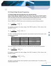
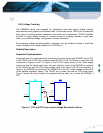
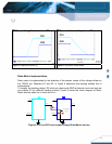
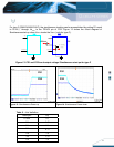
(2) Output Voltage Set-Point Adjustment by external voltage source
For DNM and DNL series, trim to Vo,set using an external voltage source, connect it
between the TRIM pin and GND pin. Please refer to the Table 3 and Table 4 as below for
the appropriate Vout. The value of Vtrim is specified as follows:
For DNM04xx and DNL04xx series
()
7525.01698.07.0
−
×−= VoutVtrim
For example, to program the output voltage of a DNL04 module to 3.3 Vdc, Vtrim is
calculated as follows:
()
VVtrim 267.07525.03.31698.07.0
=
−
×−=
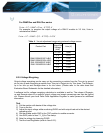
Table 3. : Vo,set adjustment range using external voltage source.
Product Part
Normal
Output Set
Voltage
(Vdc)
Vrim (V)
0.7525 Open
1.2 0.6240
1.5 0.5730
1.8 0.5220
2.5 0.4030
DNM04S0A0R10P A/B/C
DNM04S0A0R10N A/B/C
DNL04S0A0R16P A/B/C
DNL04S0A0R16N A/B/C
3.3 0.2670
9