


For DNS12xx series
()
7525.00667.07.0
−
×−= VoutVtrim V
For example, to program the output voltage of a DNS12 module to 3.3 Vdc, Vtrim is
calculated as follows
()
53.07525.03.30667.07.0
=
−×−=Vtrim V
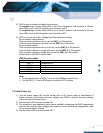
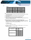
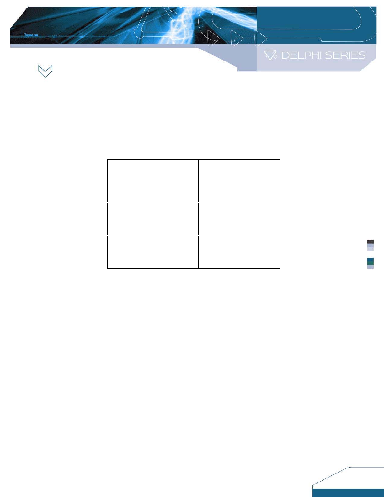
Table 4. : Vo,set adjustment range by use of external voltage source.
Product Part
Normal
Output Set
Voltage
(Vdc)
Vrim (V)
0.7525 Open
1.2 0.670
1.5 0.650
1.8 0.630
2.5 0.583
3.3 0.530
DNS12S0A0S06P A/B/C
DNS12S0A0S06N A/B/C
5.0 0.4167
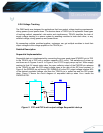
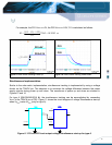
8.2.5 Voltage Margining
Output voltage margining can be carry out by connecting a resistor from the Trim pin to ground
pin for trim up and connecting a resistor from Trim pin to Output pin for Trim down. The Rmargin-
up is for trim up and Rmargin-down is for trim down. (Please refer to the data sheet and
Evaluation Board Schematic for the detailed information).
A software tool for voltage margining calculation is available to ask for. The values of Rmargin-
up and Rmargin-down for a specific output voltage and margin percentage can then be figured
out. Please consult your local Delta Field Application Engineer or sales persons for additional
information.
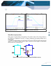
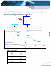
Test
1) Connect a trim resistor for a desired voltage value (Please refer to Table 1 and Table 2).
2) Turn on the fan.
3) Adjust the input voltage while monitoring DVM2 and with output load set to the desired
operating point.
4) Set the enable switch SW2 to the “ON” position to enable converter.
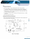
5) Use SW3 (refer to Item 7.1_6) for Trim setup.
6) Note the voltage by observing DVM3.
7) Test the Load Regulation (refer to Item 8.2.2).
10